background image

ES

7

6

76 

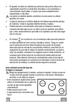
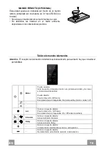
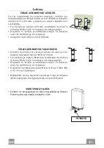
MANDO REMOTO (OPCIONAL) 

Esta  unidad  puede  ser  controlada  por  medio  de  un  mando 
remoto, alimentado por una batería  de 3 V tipo CR2032 (no 
incluida). 
• No coloque el mando remoto cerca de fuentes de calor.
• No  abandone  las  baterías  en  el  medio  ambiente,

deposítelas en los contenedores previstos.

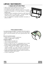
Tablero de mandos telemandos 

Atención

..: El receptor del telemando inicialmente está desactivado, para activarlo hay que consultar el 

párrafo 

Uso

Motor 

Puerta cerrada: 

Abre la puerta, enciende el motor a la primera velocidad y las luces 

a la máxima luminosidad. 

Puerta abierta: 

Presión breve: On /Off motor  

Si se presiona por 2 segundos: Cierra la puerta y motor + luces = off 

Luz 

Sólo con la puerta abierta: 

Presión breve: On / Off luces.  

Si se presiona por 2 segundos: On / Off luces de cortesía 

Intensiva 

Sólo con la puerta abierta: 

Activa la función intensiva 

Delay 

Sólo con la puerta abierta: 

Activa la función Delay 

Sólo con la puerta abierta: 

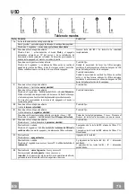
Incrementa la velocidad de ejercicio a cada presión. 

Sólo con la puerta abierta: 

Decrementa la velocidad de ejercicio a cada presión. 

Summary of Contents for FABULA EVO+BK A90

Page 1: ...Instructions Manual Manuel d Instructions Bedienungsanleitung Manual de instrucciones Εγχειρίδιο οδηγιών Руководство по эксплуатации ...

Page 2: ...SINFORMATIONEN 41 CHARAKTERISTIKEN 44 MONTAGE 46 BEDIENUNG 56 REINIGUNG UND WARTUNG 58 ÍNDICE INFORMACIÓN DE SEGURIDAD 60 CARACTERÍSTICAS 63 INSTALACIÓN 65 USO 75 LIMPIEZA Y MANTENIMIENTO 77 ΠΕΡΙΕΧΟΜΕΝΑ ΣΥΜΒΟΥΛΕΣ ΚΑΙ ΣΥΣΤΑΣΕΙΣ 79 ΧΑΡΑΚΤΗΡΙΣΤΙΚΑ 82 ΕΓΚΑΤΑΣΤΑΣΗ 84 ΧΡΗΣΗ 94 ΚΑΘΑΡΙΣΜΟΣ ΚΑΙ ΣΥΝΤΗΡΗΣΗ 96 УКАЗАТЕЛЬ ИНФОРМАЦИЯ ПО БЕЗОПАСНОСТИ 98 ХАРАКТЕРИСТИКИ 101 УСТАНОВКА 103 ЭКСПЛУАТАЦИЯ 113 ОЧИСТКА И ...

Page 3: ...height please refer to the paragraphs on working dimensions and installation If the instructions for installation for the gas hob specify a greater distance this must be respected Check that the mains voltage corresponds to that indicated on the rating plate fixed to the inside of the hood Means for disconnection must be incorporated in the fixed wiring in accordance with the wiring rules For Clas...

Page 4: ...to be adopted for fume discharging it is important to closely follow the regulations provid ed by the local authorities WARNING Before installing the Hood remove the protective films Use only screws and small parts in support of the hood WARNING Failure to install the screws or fixing device in accordance with these instructions may result in electrical hazards Do not look directly at the light th...

Page 5: ...all be handed over to the applicable collection point for the recycling of electrical and electronic equipment By ensuring this product is disposed of correctly you will help prevent potential negative consequences for the environment and human health which could otherwise be caused by inappropriate waste handling of this product For more detailed information about recycling of this product please...

Page 6: ...with Controls Light Filters 2 1 Motor unit 3 1 Electric unit 4 1 Front Frame Ref Q ty Installation Components 7 1 2 Splashback Fixing Bracket 7 2 2 Hob Fixing Bracket 7 3 2 Side Bracket 12a 16 Screws 3 5 x 9 5 12b 6 Screws M4 x 8 12c 6 Screws 4 x 15 Q ty Documentation 1 Instruction Manual ...

Page 7: ...EN 7 7 Dimensions 512 794 520 802 537 880 537 880 512 794 520 802 ...

Page 8: ... Sequence of operations Installation Drilling the Support Surface and Fitting the Hood Connections Functional Check Disposal of Packaging Drilling the Support Surface 109 812 IMPORTANT The distance between the opening made for the cooker hob and the one for the suction device must be minimum 3cm maximum 5cm according to the strength of the material used for the top ...

Page 9: ...od Canopy see paragraph on Fixing the Motor Unit Insert the Hood Canopy from below into the support worktop drilled as described above With the aid of a sup port lift the Hood Can opy until the front comes out of the Work top Insert the Brackets 7 2 as indicated in the figure into the slots provided and fix them with the screws 12a provided Centre the Hood Canopy with respect to the Cooking Hob sl...

Page 10: ...py must be removed and replaced at the front and the Cable with cable raceway for connection of the Motor must also be repositioned using the slot provided on each side A Insert the Hood Canopy into the cooker top drilled as described above Centre the Hood Canopy with respect to the Cooking Hob slot Fix the Hood Canopy with the 2 screws 12c provided Warning If the cooker top is made from a materia...

Page 11: ...e tightening the Brackets completely make all the adjustments to allow them to rest on the lower base of the worktop to avoid deformation of the upper brackets 7 2 as shown in the figure With the aid of a spirit level set the Hood Canopy level vertically and fix it to the Lower Surface using 2 screws 12c provided Tighten the screws 12a completely ...

Page 12: ...Canopy using the screws 12b provided without tightening completely Using the screws 12c provided fasten the other part of the brackets 7 3 either to the side walls of the unit or to the lower part of the cooker top 12b 7 3 12b 7 3 12c Tighten the screws 12c and 12b completely ...

Page 13: ... Subsequently according to where the air outlet opening has been created on the unit the Motor Unit can be turned by 90 at a time so as to allow the air to come out on all 4 sides in correspondence with the opening in Unit 2 Connect the connector from the Hood Canopy to theMotor Unit connection Screw the Motor Unit to the Hood Canopy using the screws 12a and 12b provided as shown in the figure ...

Page 14: ... Unit so take care not to make mistakes when connecting up Fix the Electric Unit to the Hood Canopy using the screws 12a provided The position indicated in the figure is only an option as if necessary it may also be fitted on the left of the Hood Canopy or even left free on the base of the unit if there areno structuralor safety problems involved Warning Donotinstalltheproductin such awaythatthewi...

Page 15: ...AIR OUTLET RECIRCULATION VERSION Connect the Flange to the air outlet opening using a rigid or flexible pipe of ø120 or 150 mm To connect using a ø120 mm pipe insert the reduction Flange 9 onto the Hood canopy outlet Fasten the pipe using suitable pipe clamps The materials re quired to do so are not provided Fix the directional Grid 8 on the outlet using 2 screws 12e 2 9 x 9 5 provided Make sure t...

Page 16: ...nge guards from the corners of the glass Take the front Frame and insert it from above making sure that its tabs insert into the slots provided on the Hood and sliding it to the left Warning All the tabs must be inserted Use a tool hammer to tap all along the front Frame from right to left until it is completely flush A piece of wood or similar element can be inserted between the hammer and the fr...

Page 17: ...EN 1 7 17 Surround Suction Panel Open the Hood Door see USE Remove the 2 strips of adhesive tape fastening the panel during transport ...

Page 18: ...ive speed This speed is timed to run for 6 minutes At the end of this time the systemwill return to the speed set previously It is disabled by pressing the same button again turning the motor offor closing the door Flashing LED button D Only works with the Door Open Activates speed three Fixed LED button E Only works with the Door Open Activates Deactivates speed two Fixed LED button Works both wi...

Page 19: ...ee the para graph Use Motor Door Closed Opens the door turns the motor on at speed one and turns the lights on at maximum intensity Door Open Brief pressure Motor On Off Pressed for 2 Seconds Closes the Door and Motor Lights Off Light Only with Door Open Brief pressure Lights On Off Pressed for 2 Seconds Courtesy lights On Off Intensive Only with Door Open Activates the Intensive function Delay On...

Page 20: ...be cleaned whenever button B lights up or at least once every 2 months use or more frequently if use is particularly intensive Resetting the alarm signal Turn the Lights and the Suction Motor off Press and hold button B for 2 seconds Cleaning the Filters Open the Door see USE Open the Comfort panel by pulling it Remove the Filters one at a time pushing them towards the back of the unit and at the ...

Page 21: ...ress and hold button F for 2 seconds LED B flashes twice Activated Charcoal Filter saturation alarm ACTIVATED LED B flashes once Activated Charcoal Filter saturation alarm DEACTIVATED CHANGING THE ACTIVATED CHARCOAL FILTER Resetting the alarm signal Turn the Lights and the Suction Motor off Press and hold button B for 2 seconds Changing the Filter Remove the comfort panel Remove the Metal grease f...

Page 22: ...eur inférieure voir le paragraphe concernant les dimensions de travail et l installation Si les instructions d installation du plan de cuisson à gaz spécifient une distance supérieure à celle indiquée ci dessus veuillez impérativement en tenir compte Assurez vous que la tension du secteur correspond à celle indiquée sur la plaque des caractéristiques apposée à l intérieur de la hotte Les dispositi...

Page 23: ... établis par les autorités locales AVERTISSEMENT Avant d installer la hotte retirer les films de protection Utilisez exclusivement des vis et des petites fournitures du type adapté pour la hotte AVERTISSEMENT toute installation de vis et de dispositifs de fixation non conformes à ces instructions peut entraîner des risques de décharges électriques Ne pas observer directement avec des instruments o...

Page 24: ...omme déchet ménager normal Lorsque ce produit doit être éliminé veuillez le remettre à un centre de collecte prévu pour le recyclage du matériel électrique et électronique En vous assurant que cet appareil est éliminé correctement vous participez à prévenir des conséquences potentiellement négatives pour l environnement et pour la santé qui risqueraient de se présenter en cas d élimination inappro...

Page 25: ...mmandes éclairage filtres 2 1 Groupe moteur 3 1 Groupe électrique 4 1 Cadre frontal Réf Q té Composants d installation 7 1 2 Bride de fixation au fond 7 2 2 Bride de fixation au plan 7 3 2 Bride latérale 12a 16 Vis 3 5 x 9 5 12b 6 Vis M4 x 8 12c 6 Vis 4 x 15 Q té Documentation 1 Manuel d instructions ...

Page 26: ...FR 2 6 26 Encombrement 512 794 520 802 537 880 537 880 512 794 520 802 ...

Page 27: ...uence des opérations d installation Perçage du plan de support et montage de la hotte Connexions Contrôle fonctionnel Élimination des emballages Perçage du plan de support 109 812 IMPORTANT La distance entre le trou pratiqué pour la table de cuisson et celui pour l appareil d aspiration doit être de 3 cm minimum et de 5 cm maximum en fonction de la résistance du matériau utilisé pour le haut ...

Page 28: ...upe moteur au corps de hotte Voir para graphe Fixation du groupe moteur Enfiler le corps de hotte en passant sous le plan de sup port précédemment percé À l aide d un support soule ver le corps de hotte jusqu à ce que l élément frontal sorte du plan Enfiler les brides 7 2 comme indiqué dans la fi gure dans les trous prévus et les fixer avec les vis 12a fournies Centrer le corps de hotte par rappor...

Page 29: ...uchon déjà fixé sur le dos du corps de hotte et le remonter frontalement Remettre aussi en place le câble avec le passe câble pour la con nexion du moteur en passant par le trou prévu de chaque côté A Enfiler le corps de hotte dans le plan de support précédemment percé Centrer le corps de hotte par rapport au trou du plan de cuisson Fixer le corps de hotte avec 2 vis 12c four nies Attention Si le ...

Page 30: ...ment les brides de support effectuer les réglages leur permettant de s appuyer sur la base inférieure du plan en évitant la déformation des brides de support supérieures 7 2 comme indiqué dans la figure À l aide d un niveau niveler verticalement le corps de hotte et le fixer au plan inférieur avec 2 vis 12c fournies Fixer définitivement les vis 12a 12c 12a 7 1 12a 7 1 ...

Page 31: ... au corps de hotte avec les vis 12b fournies sans les serrer Avec les vis 12c fournies serrer l autre côté des brides 7 3 soit aux parois latérales du meuble soit à la partie inférieure du plan de cuisson 12b 7 3 12b 7 3 12c Fixer définitivement les vis 12c et 12b ...

Page 32: ...itionné Ensuite selon l endroit où a été réalisé le trou de sortie de l air sur le meuble le groupe moteur pourra tourner de 90 à la fois afin de permettre la sortie de l air des quatre côtés en correspondance de celui du meuble 2 Relier le connecteur venant du corps de hotte à la connexion du groupe moteur Serrer ensuite le groupe moteur au corps de hotte avec les vis 12a et 12b fournies comme in...

Page 33: ...quent prenez garde de ne pas vous tromper lors des connexions Fixer le groupe électrique au corps de hotte avec les vis 12a fournies La position indiquée dans la figure est seulement une option si nécessaire il peut également être monté à gauche du corps de hotte ou même être laissé libre sur la base du meuble s il n y a pas d empêchements structurels ou de sécurité Attention ne pas installer le p...

Page 34: ...150 9 ø120 SORTIE AIR VERSION FILTRANTE Relier la bride au trou de sortie de l air avec un tube rigide ou flexible de ø 120 ou 150 mm Pour la liaison avec le tube ø 120 mm insérer la buse de réduction 9 sur la sortie du corps de hotte Fixer le tube avec des colliers serre tube adaptés Le matériel nécessaire n est pas fourni Fixer la grille orientée 8 sur la sortie à l aide de 2 vis 12e 2 9 x 9 5 f...

Page 35: ...adre Retirer les protections en mousse des coins du verre Saisir le cadre frontal et l enfiler par le haut en veillant à ce que ses languettes s insèrent dans les trous prévus sur la hotte puis faire coulisser le cadre vers la gauche Attention toutes les languettes doivent être insérées Taper sur le cadre frontal de droite à gauche à l aide d un outil marteau jusqu en butée Pour ne pas l abîmer vo...

Page 36: ...FR 3 6 36 Panneau aspiration périmétrale Ouvrir la porte de la hotte Voir paragraphe Utilisation Retirer les deux bandes de ru ban adhésif qui fixent le pan neau seulement durant le trans port ...

Page 37: ...alide la vitesse intensive Cette vitesse est temporisée à 6 minutes À la fin de ce délai le système retourne à la vitesse précédemment réglée Pour la désactiver appuyer sur cette même touche couper le moteur ou fermer la porte Touche led clignotante D Fonctionne seulement avec la porte ouverte Active la troisième vitesse Touche led fixe E Fonctionne seulement avec la porte ouverte Active Désactive...

Page 38: ...on Moteur Porte fermée Ouvre la porte branche le moteur à la première vitesse et l éclairage à l intensité maximum Porte ouverte Appui bref On Off Moteur Appuyée pendant 2 secondes Ferme la porte et Moteur Éclairage Off Éclairage Seulement avec la porte ouverte Appui bref On Off Éclairage Appuyée pendant 2 secondes On Off Lumières de courtoisie Intensive Seulement avec la porte ouverte Active la f...

Page 39: ...vent être lavés lorsque la touche B s allume ou au moins tous les 2 mois d utilisation environ ou plus souvent en cas d utilisation particu lièrement intensive Reset du signal d alarme Éteindre les lumières et couper le moteur d aspiration Appuyer sur la touche B pendant 2 secondes Nettoyage des filtres Ouvrir la porte Voir paragraphe Utilisation Ouvrir le Comfort Panel en le tirant Retirer les fi...

Page 40: ...ndant 2 secondes 2 clignotements touche led B Alarme saturation filtre à charbon actif ACTIVÉE 1 clignotement touche led B Alarme saturation filtre à charbon actif DÉSACTIVÉE REMPLACEMENT DU FILTRE ANTI ODEUR À CHARBON ACTIF Reset du signal d alarme Éteindre l éclairage et couper le moteur d aspiration Appuyer sur la touche B pendant 2 secondes Remplacement du filtre Retirer le comfort panel Retir...

Page 41: ...ige Modelle können auch niedriger installiert werden siehe Absatz Installation Sollten die Installationsanweisungen des gasbetriebenen Kochfelds einen größeren Abstand als oben angegeben vorsehen ist dies zu berücksichtigen Sicherstellen dass die Netzspannung der auf dem Typenschild angegebenen Spannung entspricht Das Typenschild ist im Inneren der Haube angebracht Trennvorrichtungen müssen in der...

Page 42: ...chen Behörden streng einzuhalten WARNUNG Bevor die Haube installiert wird die Schutzfolien abziehen Nur für die Abzugshaube geeignete Schrauben und Kleinteile verwenden WARNUNG Die mangelnde Verwendung von Schrauben und Befestigungselementen gemäß der vorliegenden Anleitung kann zu Stromschlaggefahr führen Nicht direkt mit optischen Instrumenten Fernglas Lupe usw in das Licht schauen Auf keinen Fa...

Page 43: ...ckung weist darauf hin dass das Gerät nicht als normaler Hausmüll entsorgt werden darf Das ausrangierte Gerät muss vielmehr bei einer speziellen Sammelstelle für elektrische und elektronische Geräte abgegeben werden Mit der vorschriftsmäßigen Entsorgung des Gerätes trägt der Benutzer dazu bei schädliche Auswirkungen auf Umwelt und Gesundheit zu vermeiden Weitere Informationen zum Recycling dieses ...

Page 44: ...leuchtung Filter 2 1 Motorgruppe 3 1 Elektrik 4 1 Frontrahmen Bez Menge Installationskomponenten 7 1 2 Bügel für die Befestigung am Boden 7 2 2 Bügel für die Befestigung am Kochfeld 7 3 2 Seitlicher Bügel 12a 16 Schrauben 3 5 x 9 5 12b 6 Schrauben M4 x 8 12c 6 Schrauben 4 x 15 Menge Dokumentation 1 Betriebsanleitung ...

Page 45: ...DE 4 5 45 Platzbedarf 512 794 520 802 537 880 537 880 512 794 520 802 ...

Page 46: ...nstallationsarbeiten Bohrung der Kochfläche und Montage der Haube Anschlüsse Funktionskontrolle Entsorgung des Verpackungsmaterials Bohrung der Auflagefläche 109 812 WICHTIG Der Abstand zwischen der Öffnung für das Kochfeld und der Öffnung für die Abzugshaube muss mindestens 3cm maximal 5cm betragen je nach der Festigkeit des Materials aus dem das Oberteil besteht ...

Page 47: ...m Haubenkörper befestigen SieheAb satz Befestigung derMotoreinheit Den Haubenkörper von unten in die zuvor gebohrte Auflagefläche schieben Mit Hilfe einer Halterung den Haubenkörper anheben bis die Frontseite aus der Kochfläche her vorragt Die Bügel 7 2 wie abgebildet in die speziellen Ösen einsetzen und mitden mitgelieferten Schrauben 12a befestigen Den Haubenkörper mitder Öse der Kochfläche zent...

Page 48: ...ebrachte Deckel ausgebautund an der Frontseite montiert Ebenso das Kabel mit Lippklampe fürden Anschlussdes Motors neu positionieren wobeidie Öse A verwendet wird die an beiden Seiten vorbereitet ist Den Haubenkörper in die zuvor gebohrte Kochfläche schieben Den Haubenkörper mitder Öse der Kochfläche zentrieren Den Haubenkörper mit den beiden mitgeliefer ten Schrauben 12c be festigen Achtung Falls...

Page 49: ...l diese so regulieren dass sie an der unteren Basis der Kochfläche aufliegen und die oberen Bügel 7 2 nicht deformiert werden wie in der Ab bildung gezeigt Mit einer Wasserwaage den Haubenkörper vertikal ausrichten und mit den mitgelieferten beiden Schrauben 12c an der unteren Kochfläche befestigen Die Schrauben 12a definitiv festziehen 12c 12a 7 1 12a 7 1 ...

Page 50: ...uben 12b am Haubenkörper befestigen ohne festzuziehen Den anderen Teil der Bügel 7 3 mit den mitgelieferten Schrauben 12c entweder an den Sei tenwänden des Möbels oder an der Unterseite der Kochfläche befestigen 12b 7 3 12b 7 3 12c Die Schrauben 12c und 12b definitiv festschrauben ...

Page 51: ... Danach kann die Motoreinheit entsprechend derPosition der Ab luftöffnung am Möbel umjeweils 90 gedreht werden so dass der Luftauslass an allen 4 Seiten auf Höhe der Öffnung am Möbel 2 ermöglicht wird Den aus dem Haubenkörper austretenden Verbinder mit dem Anschluss der Motoreinheit verbinden Danach die Motoreinheit mitden mitge lieferten Schrauben 12aund 12b wie ab gebildet am Haubenkörper anschr...

Page 52: ...n dass nicht falsch angeschlossen wird Die Elektrik mit den mitgelieferten Schrau ben 12a am Haubenkörper befestigen Die abgebildete Position ist lediglich ein Vorschlag weil die Elektrik bei Bedarf auch links am Haubenkörper montiert oder sogar frei an der Basis des Möbels belassen werden kann sofern keine strukturellen Hindernisse oder Sicherheitsbedenken vor liegen Achtung BeiderInstallationdar...

Page 53: ... Flansch mit einem starren oder flexiblen Rohr mit ø 120 oder 150 mm an die Abzugsöffnung anschließen Für den Anschluss mit einem Rohr mit ø 120 den Reduzierflansch 9 am Auslass am Haubenkörper einsetzen Das Rohr mit geeigneten Rohrschellen fixieren Das hierzu erforderliche Material wird nicht mitgeliefert Das Luftstromrichtungsgitter 8 mit den 2 mitgelieferten Schrauben 12e 2 9 x 9 5 am Auslass b...

Page 54: ...ie Schutzecken aus Schaum stoff von der Glasscheibe neh men Den Frontrahmen zur Hand nehmen von oben so einschie ben dass seine Laschen in die Ösen an der Haube passen und nach links gleiten lassen Achtung Alle Laschen müssen eingeschoben sein Mit einem Werkzeug Ham mer von rechts nach links auf den Frontrahmen klopfen bis er sich am Anschlag befindet Um Beschädigungen zu ver meiden kann ein passe...

Page 55: ...DE 5 5 55 Umlaufendes Saugpaneel Die Klappe öffnen siehe Ab satz Gebrauch Die beiden Klebestreifen ent fernen welche das Paneel wäh rend des Transports fixieren ...

Page 56: ...eseGeschwindigkeitistauf6Minutenzeitgeregelt NachAblaufdieserZeit kehrtdasSystemzuderzuvoreingestelltenGeschwindigkeitzurück WirddurchDrückenderselbenTaste AbstellendesMotorsoderSchließender Klappedeaktiviert LEDTasteblinkt D FunktioniertnurbeigeöffneterKlappe SchaltetdiedritteBetriebsgeschwindigkeitein LEDTastebleibendeingeschaltet E FunktioniertnurbeigeöffneterKlappe SchaltetdiezweiteBetriebsges...

Page 57: ...t die Klappe und schaltet den Motor bei der ersten Geschwindigkeitsstufe und stärkster Beleuchtung ein Klappe offen Kurzes Drücken On Off Motor 2 Sekunden langes Drücken Schließt die Klappe und Motor Beleuchtung Off Beleuchtung Nur bei geöffneter Klappe Kurzes Drücken On Off Beleuchtung 2 Sekunden langes Drücken On Off Notbeleuchtung Intensivgeschwindigkeit Nur bei geöffneter Klappe Aktiviert die ...

Page 58: ...gewaschen werden sobald sich die Taste B einschaltet oder mindestens alle 2 Monate oder auch öfter je nach Intensität des Gebrauchs Reset des Alarmsignals Die Beleuchtung und den Absaugmotor abstellen Die Taste B 2 Sekunden lang drücken Reinigung der Filter Die Klappe öffnen siehe Gebrauch Das Komfort Paneel herausziehen Die Filter einzeln ausbauen indem sie in den hinteren Teil der Gruppe geschob...

Page 59: ...angdrücken Zweimaliges Blinken der LEDB Sättigungsalarm Aktivkohlefilter AKTIVIERT Einmaliges Blinken der LED B Sättigungsalarm Aktivkohlefilter DEAKTIVIERT AUSWECHSELN DES AKTIVKOHLE GERUCHSFILTERS Reset des Alarmsignals Die Beleuchtung und den Absaugmotor abstellen Die Taste B 2 Sekunden lang drücken Auswechseln des Filters Das Komfort Paneel ausbauen Die Fettfilter aus Metall entfernen Die Filt...

Page 60: ... altura inferior véase la sección sobre dimensiones de trabajo e instalación Si en las instrucciones de montaje de la placa de cocción a gas se indica una distancia mayor que la indicada anteriormente debe tenerse en cuenta Compruebe que la tensión de red coincide con la indicada en la placa de características del interior de la campana Los dispositivos de desconexión deben instalarse en la instal...

Page 61: ...os es importante cumplir escrupulosamente las normas establecidas por las autoridades locales ADVERTENCIA Retire la película protectora antes de instalar la campana Utilice únicamente tornillos y herramientas que sean adecuados para la campana ADVERTENCIA Si no se instalan tornillos o sujetadores de acuerdo con estas instrucciones se puede producir una descarga eléctrica No observar directamente c...

Page 62: ...que el producto a eliminar debe recogerse en un punto de recogida adecuado para el reciclaje de componentes eléctricos y electrónicos Al asegurarse de que este producto se deseche correctamente ayudará a evitar las posibles consecuencias negativas para el medio ambiente y la salud que podrían derivarse de una eliminación inadecuada de este producto Para obtener información más detallada sobre el r...

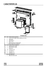
Page 63: ...4 1 Marco frontal 8 1 Rejilla de dirección de salida del aire 9 1 Brida de reducción ø 150 120 mm Ref Cant Componentes de instalación 7 1 2 Brida de fijación al fondo 7 2 2 Brida de fijación al plano 7 3 2 Brida lateral 12a 16 Tornillos 3 5 x 9 5 12b 6 Tornillos M4 x 8 12c 6 Tornillos 4 x 15 12e 2 Tornillos 2 9 x 9 5 Cant Documentación 1 Manual de instrucciones ...

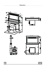
Page 64: ...ES 6 4 64 Dimensiones 512 794 520 802 537 880 537 880 512 794 520 802 ...

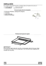
Page 65: ...erna Secuencia operaciones de instalación Perforación del plano y montaje de la campana Conexiones Control funcional Eliminación embalajes Perforación del plano de soporte 109 812 IMPORTANTE Entre el orificio para la placa de cocción y el del aparato extractor tiene que haber una distancia mínima de 3 cm y máxima de 5 cm en función de la resistencia del material de la encimera ...

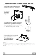
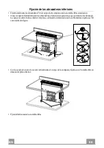
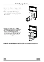
Page 66: ... al cuerpo de la campana Ver párra fo Fijación del grupo motor Introducir el cuerpo dela campana por abajo en el plano de soporte anteriormente perforado Con la ayudade un soporte alzar el cuerpo de la campana hasta que la parte frontal salga del plano Insertar las bridas7 2 como se indica en la figura en losojales y fijarlas con los tornillos12a en dotación Centrar el cuerpo de la campana respect...

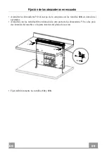
Page 67: ...a parte traseradel cuer po de la campana y volverlo a montar frontalmente Volver a colocar también el cable con pasacable para la conexión del motorutilizando el ojal dispuesto en cada lado A Introducir el cuerpo en el plano de cocción ante riormenteperforado Centrar el cuerpo de la campana respecto al ojal del plano de cocción Fijar con 2 tornillos12c en dota ción el cuerpo de la campana Atención...

Page 68: ... abrazaderas efectuar las regulaciones que permiten a las abrazade ras apoyarse sobre la base inferior del plano evitando la deformación de las abrazaderas superiores 7 2 como indica la figura Con la ayuda de un nivel novelar verticalmente el cuerpo de la campana y fijarlo con 2 tornillos 12c en dotación al plano inferior Fijar definitivamente los tornillos12a 12c 12a 7 1 12a 7 1 ...

Page 69: ... de la campana con los tornillos 12b en dotación si apretarlas Atornillar con los tornillos 12c en dotación la otra parte de las abrazaderas 7 3 o a las pare des laterales del mueble o a la parte inferior del plano de cocción 12b 7 3 12b 7 3 12c Fijar definitivamente los tornillos 12c y 12b ...

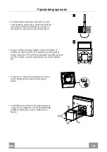
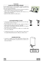
Page 70: ...al lugar donde se haya realizado el orificio de salida de aire del mueble se puede girar el grupo motor de 90º en 90º para permitir la salida del aire por los 4 lados en correspondencia con el del mueble 2 Conectar el conector procedente el cuerpo de la campana a la conexión del grupo motor Atornillar sucesivamente el grupo motor al cuerpo de la campana con los tornillos 12a y 12b en dotación como...

Page 71: ...o se debe poner atención a no equivocar las conexiones Fijar el grupo eléctrico al cuerpo de la campana con los tornillos 12a en dotación La posición indicada en la figura es sólo una opción Si es necesario se puede montar también a la izquierda del cuerpo de la campana o incluso se puede dejar libre sobre la base móvil si no hay problemas estructurales o de seguridad Atención No instalar el produ...

Page 72: ...ANTE Conectar la brida al orificio de salida del aire con un tubo rígi do o flexible de ø120 o 150 mm Para la conexión con el tubo ø120 mm insertar la brida de reducción 9 en la salida del cuerpo de la campana Fijar el tubo con adecuadas abrazaderas ajustables El material necesario no viene en dotación Fijar la rejilla direccionada 8 en la salida con 2 tornillos 12e 2 9 x 9 5 en dotación Comprobar...

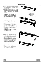
Page 73: ...tar las protecciones de es ponja de las esquinas del vidrio Tomar el marco frontal e intro ducirlo por arriba cuidando de que sus lengüetas se inserten en los ojales preparados en la campana y desplazarlo hacia la izquierda Atención Todas las lengüetas se deben insertar Batir en el marco frontal de de recha a izquierda con la ayuda de una herramienta martillo hasta llegar al tope Para no dañar el ...

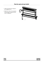
Page 74: ...ES 7 4 74 Panel de aspiración perimetral Abrir la puerta de la campana Ver párrafo Uso Quitar las 2 tiras de cinta adhe siva que fijan el panel sólo du rante el transporte ...

Page 75: ...ocidad Intensiva Dicha velocidad está temporizada en 6 minutos Al final del tiempo elsistema regresa a la velocidad implementada precedentemente Se desactiva presionando la misma tecla apagando el motor o cerrando la puerta Tecla led intermitente D Funciona sólo con la puerta abierta Activa la tercera velocidad Tecla led fijo E Funciona sólo con la puerta abierta Activa desactiva la segunda veloci...

Page 76: ...párrafo Uso Motor Puerta cerrada Abre la puerta enciende el motor a la primera velocidad y las luces a la máxima luminosidad Puerta abierta Presión breve On Off motor Si se presiona por 2 segundos Cierra la puerta y motor luces off Luz Sólo con la puerta abierta Presión breve On Off luces Si se presiona por 2 segundos On Off luces de cortesía Intensiva Sólo con la puerta abierta Activa la función ...

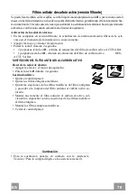
Page 77: ...lavados cuando se enciende la tecla B o al menos cada 2 meses de uso aproximada mente o más frecuentemente para un uso particularmente inten so Reset de la señal de alarma Apagar las luces y el motor de aspiración Pulsar la tecla B durante 2 segundos Limpieza de filtros Abrir la puerta ver párrafo Uso Abrir el comfort panel tirándolo Quitar los filtros uno por vez empujándolos hacia la parte poste...

Page 78: ...2 segundos 2 parpadeos tecla Led B Alarma de saturación del filtro de carbón activo ACTIVADA 1 parpadeo tecla Led B Alarma de saturación del filtro de carbón activo DES ACTI VADA SUSTITUCIÓN DEL FILTRO ANTIOLOR AL CARBÓN ACTIVO Reset de la señal de alarma Apagar las luces y el motor de aspiración Pulsar la tecla B durante 2 segundos Sustitución filtro Quitar el comfort panel Quitar los filtros ant...

Page 79: ... ύψος Ανατρέξτε στην παράγραφο µε τις διαστάσεις λειτουργίας και εγκατάστασης Αν οι οδηγίες εγκατάστασης της µονάδας εστιών µε υγραέριο υποδεικνύουν ότι απαιτείται απόσταση µεγαλύτερη από εκείνη που αναφέρεται παραπάνω είναι απαραίτητο να τις λάβετε υπόψη Βεβαιωθείτε ότι η τάση του δικτύου αντιστοιχεί στην τιµή που αναγράφεται στην πινακίδα χαρακτηριστικών στο εσωτερικό του απορροφητήρα Τα συστήµα...

Page 80: ...είας που πρέπει να εφαρµοστούν για την απαγωγή των καπναερίων είναι σηµαντικό να τηρούνται σχολαστικά οι κανονισµοί των τοπικών φορέων ΠΡΟΕΙ ΟΠΟΙΗΣΗ πριν εγκαταστήσετε τον απορροφητήρα αφαιρέστε τις προστατευτικές µεµβράνες Χρησιµοποιείτε µόνο βίδες και εξαρτήµατα κατάλληλου τύπου για τον απορροφητήρα ΠΡΟΕΙ ΟΠΟΙΗΣΗ η µη τοποθέτηση των βιδών και των συστηµάτων στερέωσης σύµφωνα µε τις παρούσες οδηγ...

Page 81: ...ισµένο οικιακό απόρριµµα Το προϊόν προς διάθεση πρέπει να παραδίδεται σε ένα κατάλληλο κέντρο συλλογής για την ανακύκλωση των ηλεκτρικών και ηλεκτρονικών συσκευών Φροντίζοντας για τη σωστή διάθεση αυτού του προϊόντος συµβάλλετε στην αποφυγή πιθανών αρνητικών επιπτώσεων για το περιβάλλον και την υγεία που µπορεί να οφείλονται στην ακατάλληλη διάθεσή του Για λεπτοµερέστερες πληροφορίες σχετικά µε τη...

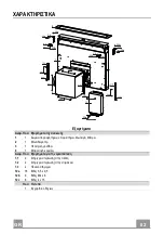
Page 82: ... Φωτισµό Φίλτρα 2 1 Μονάδα µοτέρ 3 1 Ηλεκτρική µονάδα 4 1 Μπροστινή κορνίζα Αναφ Ποσ Εξαρτήµατα για την εγκατάσταση 7 1 2 Στήριγµα στερέωσης στην πλάτη 7 2 2 Στήριγµα στερέωσης στην επιφάνεια 7 3 2 Πλαϊνό στήριγµα 12a 16 Βίδες 3 5 x 9 5 12b 6 Βίδες M4 x 8 12c 6 Βίδες 4 x 15 Ποσ Έντυπα 1 Εγχειρίδιο οδηγιών ...

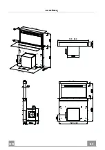
Page 83: ...GR 8 3 83 ιαστάσεις 512 794 520 802 537 880 537 880 512 794 520 802 ...

Page 84: ...Σειρά ενεργειών για την εγκατάσταση ιάτρηση επιφάνειας και τοποθέτηση απορροφητήρα Συνδέσεις Έλεγχος λειτουργίας ιάθεση συσκευασίας ιάτρηση επιφάνειας στήριξης 109 812 ΣΗΜΑΝΤΙΚΟ Η απόσταση ανάμεσα στην οπή που θα κάνετε για τη μονάδα εστιών και σε εκείνη για τη συσκευή αναρρόφησης πρέπει να είναι ελάχ 3 cm μέγ 5 cm ανάλογα με την αντοχή του υλικού που έχει χρησιμοποιηθεί για τον πάγκο ...

Page 85: ...τε τηµονάδαµοτέρστοσώµααπορροφητήρα βλ παράγραφοΣτερέωσηµονάδας µοτέρ Περάστε το σώµααπορροφητήρααπόκάτωστηνεπιφάνεια στήριξης πουέχετεήδητρυπήσει Μετηβοήθειαενός στηρίγµατος σηκώστε το σώµα απορροφητήραέως ότουηπρόσοψη προεξέχειαπό την επιφάνεια Περάστε ταστηρίγµατα7 2 όπως δείχνειηεικόνα στα ειδικάανοίγµατακαιστερεώστε ταµετις βίδες12aτου εξοπλισµού Κεντράρετε το σώµααπορροφητήραως προς το άνοιγ...

Page 86: ... µέρος του σώµατος απορροφητήρα και να το τοποθετήσετε από εµπρός καθώς και να τοποθετήσετε το καλώδιο µε στυπειοθλίπτη για τη σύνδεση του µοτέρ χρησιµοποιώντας το άνοιγµα που υπάρχει σε κάθε πλευρά A Περάστε το σώµα απορροφητήρα στην επιφάνεια εστιών που έχετε ήδη τρυπήσει Κεντράρετε το σώµα απορροφητήρα ως προς το άνοιγµα της µονάδας εστιών Στερεώστε το σώµα απορροφητήρα µε 2 βίδες 12c του εξοπλ...

Page 87: ...τηρίγµατα εκτελέστε τις ρυθµίσεις που θα επιτρέψουν στα στηρίγµατα να ακουµπήσουν στην κάτω βάση της επιφάνειας αποφεύγοντας την παραµόρφωση των πάνω στηριγµάτων 7 2 όπως δείχνει η εικόνα Με ένα αλφάδι αλφαδιάστε κατακόρυφα το σώµα απορροφητήρα και στερεώστε το µε 2 βίδες 12c του εξοπλισµού στην κάτω επιφάνεια Σφίξτε οριστικά τις βίδες 12a 12c 12a 7 1 12a 7 1 ...

Page 88: ...του απορροφητήρα µε τις βίδες 12b του εξοπλισµού χωρίς να τις σφίξετε Βιδώστε µε τις βίδες 12c του εξοπλισµού την άλλη πλευρά των στηριγµάτων 7 3 ή στα πλαϊνά τοιχώµατα του επίπλου ή στο κάτω µέρος της επιφάνειας εστιών 12b 7 3 12b 7 3 12c Σφίξτε οριστικά τις βίδες 12c και 12b ...

Page 89: ...βρίσκεται η οπή εξόδου του αέρα στο έπιπλο µπορείτε να περιστρέψετε τη µονάδα µοτέρ κατά 90 και στη συνέχεια κατά άλλες 90 έτσι ώστε να επιτρέψετε την έξοδο του αέρα και στις 4 πλευρές σε αντιστοιχία µε εκείνη του επίπλου 2 Συνδέστε το συνδετήρα που προέρχεται από το σώµα απορροφητήρα στη σύνδεση της µονάδας µοτέρ Στη συνέχεια βιδώστε τη µονάδα µοτέρ στο σώµα του απορροφητήρα µε τις βίδες 12a και ...

Page 90: ... εποµένως προσέξτε να µην κάνετε λάθος σύνδεση Στερεώστε την ηλεκτρική µονάδα στο σώµα του απορροφητήρα µε τις βίδες 12a του εξοπλισµού Η θέση που υποδεικνύεται στην εικόνα είναι µόνο µια επιλογή επειδή αν χρειαστεί µπορεί να τοποθετηθεί και στα αριστερά του σώµατος απορροφητήρα στη βάση του επίπλου σε περίπτωση που δεν υπάρχουν εµπόδια ή θέµα ασφαλείας Προσοχή Μην τοποθετείτε τη συσκευή αφήνοντας...

Page 91: ...ακα ø150 9 ø120 ΕΞΟ ΟΣ ΑΕΡΑ ΜΟΝΤΕΛΟΥ ΑΝΑΚΥΚΛΩΣΗΣ Συνδέστε τη φλάντζα στο άνοιγµα εξόδου του αέρα µε έναν άκαµπτο ή εύκαµπτο σωλήνα Φ120 ή 150 mm Για σύνδεση µε σωλήνα Φ120 mm τοποθετήστε τη φλάντζα συστολής 9 στην έξοδο του σώµατος του απορροφητήρα Στερεώστε το σωλήνα µε κατάλληλα κολάρα Το αναγκαίο υλικό δεν διατίθεται µε τον εξοπλισµό Στερεώστε τη ρυθµιζόµενη γρίλια 8 στην έξοδο µε 2 βίδες 12e 2...

Page 92: ...ά από τις γωνιές του τζαµιού Πάρτε την µπροστινή κορνίζα και τοποθετήστε την από πάνω προσέχοντας ώστε οι προεξοχές να προσαρµόσουν στις ειδικές υποδοχές του απορροφητήρα και µετακινήστε την προς τα αριστερά Προσοχή Όλες οι προεξοχές πρέπει να προσαρµόσουν σωστά Χτυπήστε την µπροστινή κορνίζα από δεξιά προς τα αριστερά µε ένα εργαλείο σφυρί µέχρι να τερµατίσει Για να µην την καταστρέψετε µπορείτε ...

Page 93: ...GR 9 3 93 Περιµετρική µονάδα αναρρόφησης Ανοίξτε την πόρτα του απορροφητήρα βλ παράγραφο Χρήση Αφαιρέστε τις 2 αυτοκόλλητες ταινίες που στερεώνουν τη µονάδα µόνο κατά τη µεταφορά ...

Page 94: ...η 6 λεπτών Μετά την πάροδο του χρόνουαυτούτοσύστηµαεπανέρχεταιστηνπροηγούµενηεπιλεγµένηταχύτητα Απενεργοποιείται πιέζοντας το ίδιο πλήκτρο σβήνοντας το µοτέρ ή κλείνοντας την πόρτα ΠλήκτροLedαναβοσβήνει D Λειτουργείµόνοµετηνπόρταανοιχτή Ενεργοποιείτηντρίτηταχύτητα ΠλήκτροLedσταθεράαναµµένο E Λειτουργείµόνοµετηνπόρταανοιχτή Ενεργοποιεί Απενεργοποιεί τηδεύτερηταχύτητα ΠλήκτροLedσταθεράαναµµένο Λειτο...

Page 95: ... Πόρτα κλειστή Η πόρτα ανοίγει το µοτέρ ανάβει στην πρώτη ταχύτητα µε τα φώτα στη µέγιστη ένταση Πόρτα ανοιχτή Σύντοµη πίεση Ανάβει Σβήνει το µοτέρ Αν το πιέσετε για 2 δευτερόλεπτα Κλείνει την πόρτα και µοτέρ φώτα Off Φως Μόνο µε την πόρτα ανοιχτή Σύντοµη πίεση Ανάβει Σβήνει τα φώτα Αν το πιέσετε για 2 δευτερόλεπτα Ανάβει Σβήνει τα φώτα της πλαφονιέρας Έντονη Μόνο µε την πόρτα ανοιχτή Ενεργοποιεί ...

Page 96: ...να πλυθούν στο πλυντήριο πιάτων και απαιτούν πλύσιµο όταν ανάβει το πλήκτρο Β ή τουλάχιστον κάθε 2 µήνες χρήσης ή συχνότερα σε περίπτωση ιδιαίτερασυχνής χρήσης Μηδενισµός του συναγερµού Σβήστε τα φώτα και το µοτέρ αναρρόφησης Πιέστε το πλήκτρο Β για2 δευτερόλεπτα Καθαρισµός φίλτρων Ανοίξτε την πόρτα βλ παράγραφο Χρήση Ανοίξτε το Comfort Panel τραβώντας το Βγάλτε τα φίλτρα ένα ένα πιέζοντας προς το...

Page 97: ...το πλήκτρο F για 2 δευτερόλεπτα 2 αναβοσβήµατα πλήκτρου Led Β Συναγερµός κορεσµού φίλτρου ενεργού άνθρακα ΕΝΕΡΓΟΠΟΙΗΜΕΝΟΣ 1 αναβόσβηµα πλήκτρου Led Β Συναγερµός κορεσµού φίλτρου ενεργού άνθρακα ΑΠΕΝΕΡΓΟΠΟΙΗΜΕΝΟΣ ΑΝΤΙΚΑΤΑΣΤΑΣΗ ΦΙΛΤΡΟΥ ΕΝΕΡΓΟΥ ΑΝΘΡΑΚΑ Μηδενισµός του συναγερµού Σβήστε τα φώτα και το µοτέρ αναρρόφησης Πιέστε το πλήκτρο Β για 2 δευτερόλεπτα Αντικατάσταση φίλτρου Αφαιρέστε το comfort pa...

Page 98: ...здел посвященный рабочим размерам и операциям по установке прибора Если в инструкциях по установке газовой плиты сказано что расстояние до вытяжки должно быть больше указанного выше следует придерживаться предписанных размеров Проверьте соответствие напряжения сети указанному на табличке закрепленной внутри вытяжки В соответствии с нормативными правилами монтажа электропроводки в стационарной элек...

Page 99: ...е технические требования и меры безопасности для систем отведения дыма ПРЕДУПРЕЖДЕНИЕ прежде чем приступить к установке кухонной вытяжки снимите с нее защитную пленку Используйте только винты и метизы пригодные для установки вытяжного шкафа ПРЕДУПРЕЖДЕНИЕ использование винтов или зажимных устройств не соответствующих указаниям данных инструкций может привести к возникновению опасных ситуаций и к э...

Page 100: ... выбрасывать как обычный бытовой мусор Прибор подлежащий уничтожению необходимо сдать в специальный сборный пункт для повторного использования электрических и электронных компонентов Пользователь правильно сдающий прибор на переработку помогает предотвратить потенциальные негативные последствия для окружающей среды и для здоровья людей возникающие в случае неправильного его уничтожения За более по...

Page 101: ...свещением фильтрами 2 1 Двигатель 3 1 Электрооборудование 4 1 Передняя рамка Об Кол Установочные компоненты 7 1 2 Кронштейн крепления к заднику 7 2 2 Кронштейн крепления к плоскости 7 3 2 Боковой кронштейн 12a 16 Винты 3 5 x 9 5 12b 6 Винты M4 x 8 12c 6 Винты 4 x 15 Кол Документация 1 Инструкции по эксплуатации ...

Page 102: ...RU 1 0 102 Габариты 512 794 520 802 537 880 537 880 512 794 520 802 ...

Page 103: ...оследовательность операций по установке Подготовка отверстия в полке и установка вытяжки Соединения Функциональная проверка Уничтожение упаковочных материалов Подготовка отверстия в опорной плоскости 109 812 ВНИМАНИЕ Расстояние между отверстием для варочной панели и отверстием для вытяжки должно быть не менее 3 см и не более 5 см в зависимости от прочности материала из которого изготовлена столешн...

Page 104: ...здел Установка двигателя Вставьте корпус вытяжки снизу вверх через подготовленноеранее отверстие в опорной плоскости С помощью опор поднимите корпус вытяжки чтобы его передняя сторона поднялась над варочной панелью Вставьте кронштейны7 2 как показано на рисунке в специальные отверстия и закрепите их прилагаемыми винтами 12a Выставите корпус вытяжки по центру относительно отверстия над варочной пан...

Page 105: ...ь ее спереди Также измените положение провода с кабельным зажимом для соединения его с двигателем для этого пропустите его через отверстие предусмотренное с каждой стороны A Вставьте корпус вытяжки в подготовленное ранее отверстие в опорной плоскости Выставите корпус вытяжки по центру относительно отверстия над варочной панелью Закрепите корпус вытяжки 2 прилагаемыми винтами 12c Внимание если мате...

Page 106: ...затянуть крепление кронштейнов отрегулируйте их положение так чтобы они опирались на нижнее основание полки не деформируя при этом верхние кронштейны 7 2 как показано на рисунке С помощью уровня выставите корпус вытяжки по вертикали и закрепите его к нижней полке прилагаемыми в комплекте 2 винтами 12c Окончательно затяните винты 12a 12c 12a 7 1 12a 7 1 ...

Page 107: ...штейны 7 3 к корпусу вытяжки прилагаемыми в комплекте винтами 12b не затягивая Привинтите прилагаемыми винтами 12c вторую половину кронштейнов 7 3 к боковым стенкам мебели или к нижней части варочной панели 12b 7 3 12b 7 3 12c Окончательно затяните винты 12c и 12b ...

Page 108: ... положении заглушки Затем в зависимости от положения выпускного отверстия воздуха в полке двигатель можно поворачивать на 90 с тем чтобы воздух мог выходить со всех 4 сторон для совмещения с отверстием в мебели 2 Соедините разъем корпуса вытяжки с разъемом двигателя Привинтите двигатель к корпусу вытяжки прилагаемыми винтами 12a и 12b как показано на рисунке ...

Page 109: ...льны чтобы не ошибиться в их соединении Прикрепите распределительную коробку к корпусу вытяжки прилагаемыми в комплекте винтами 12a Показанное на рисунке положение распределительной коробки ориентировочно ее можно закрепить с левой стороны корпуса вытяжки или даже оставить в свободном состоянии на полке если этому не мешают особенности конструкции или условия безопасности Внимание не устанавливайт...

Page 110: ... РЕЖИМЕ ФИЛЬТРАЦИИ Соедините фланец с выпускным отверстием воздуха жесткой или гибкой трубкой ø 120 или 150 мм Для соединения с трубкой ø 120 мм вставьте переходный фланец 9 в выпускное отверстие в корпусе вытяжки Закрепите трубку специальными трубными зажимами Необходимый материал не входит в комплект поставки Закрепите регулируемую решетку 8 на выпуске воздуха 2 прилагаемыми в комплекте винтами ...

Page 111: ...ускается только в ходе установки рамки Выньте прокладки из губки из углов стекла Вставьте переднюю рамку сверху проследите чтобы язычки рамки вошли в специальные отверстия на вытяжке сдвиньте рамку влево Внимание все язычки должны находиться в отверстиях Чтобы сдвинуть переднюю рамку до упора постучите по ней справа налево инструментом молотком Чтобы не повредить рамку подложите под молоток деревя...

Page 112: ...RU 1 1 112 Панель всасывания по периметру Откройте створку вытяжки см раздел Эксплуатация Удалите 2 полоски клейкой ленты служащие только для безопасной перевозки панели ...

Page 113: ... прибор возвращается к работе на настроенной ранее скорости Отключается нажатием этой же кнопки выключением двигателя или закрытиемстворки Кнопкасмигающиминдикатором D Действуеттолькоприоткрытойстворке Включаеттретьюскорость Кнопкасгорящиминдикатором E Действуеттолькоприоткрытойстворке Включаетивыключаетвторуюскорость Кнопкасгорящиминдикатором Действует как при открытой так и при закрытой створке ...

Page 114: ...еле Использование Двигатель Створка закрыта открывает створку включает двигатель на первой скорости и освещение максимальной яркости Створка открыта Краткое нажатие Вкл Выкл двигателя При нажатии в течение 2 секунд створка закрывается освещение и двигатель выключаются Освещение Только при открытой створке краткое нажатие Вкл Выкл освещения При нажатии в течение 2 секунд Вкл Выкл ламп подсветки Инт...

Page 115: ...о мыть также в посудомоечной машине Их следует мыть когда загорается кнопка B и не реже одного раза в 2 месяца работы или даже чаще в случае особенно интенсивного использования вытяжки Сброс аварийного сигнала Выключите освещение и двигатель системы всасывания Нажмите кнопкуB в течение2 секунд Очистка фильтров Откройте створку см разделЭксплуатация Потяните на себя и откройте переднюю панель вытяж...

Page 116: ...вкеилипосленее Выключитеосвещениеидвигательвытяжного вентилятора НажмитекнопкуF на2 секунды 2 вспышкииндикатораB Сигнализация насыщения угольногофильтраВКЛЮЧЕНА 1 вспышкаиндикатораB Сигнализация насыщения угольногофильтраВЫКЛЮЧЕНА ЗАМЕНАФИЛЬТРАПРОТИВЗАПАХОВНААКТИВИРОВАННОМУГЛЕ Сбросаварийногосигнала Выключитеосвещениеидвигательсистемывсасывания НажмитекнопкуB втечение2секунд Заменафильтра Снимитеп...

Page 117: ......

Page 118: ......

Page 119: ......

Page 120: ...991 0497 156_ver4 190702 D00003515_03 ...

Reviews: