background image

EN 

USE


22

Control panel 

Turns the motor on/off at speed one

the rel

evant

 button LED turns on, and stays 

on at all speeds.

Press briefly to start the motor, if pressed by any speed the motor turns off.

W

ith all the loads turned off (Motor and Light), if activated, it signals the Filter 

saturation alarm, indicated by three LED flashing of each button.

Turns the Motor on at speed two

the rel

evant

 button LED turns on only at 2° speed.

Press and hold the button for approximately 2 seconds, with all the loads turned 

off (Motor and Lights), to turn the Activated Charcoal Filter alarm on. The LED 

flashes twice to confirm. To turn the alarm off, press the button again and hold for 

at least 2 seconds. The LED        flashes once.

Turns the lights ON/OFF and also the rel

evant

 LED.

Turns the STEAM_SYSTEM on/off

  (

turns the Vortex motor on/off 

)


When the SoS is on, the relevant LED turns on

.

With all the loads turned off (Motor and Light)

,

pressing and holding the button 

for approximately 2 seconds, the remote control is disabled, indicated by the LED 

flashing just once. Pressing again, the remote control is enabled

, indicated by the 

LED       flashing twice.

Turns the Motor on at speed three, the relevant button LED turns on only at 3° speed.

Press and hold the button for approximately 2 seconds


to turns the Motor on at 

INTENSIVE Speed, the LED flashes every 0.5”. This speed is timed to run for 6 

minutes. At the end of this time, the system returns automatically to the

speed that was set before. If it is activated with the motor turned off, it will switch 

to OFF at the end of the time. It is deactivated by pressing the same button, or any 

speed button or the button        to turn off the motor.

The Metal Grease Filter saturation


occurs

 after the Hood has been in 

operation for 100 working hours

indicated by the LED       flashing 

every 1"

The Activated Charcoal Filter saturation


occurs

 after the Hood has been 

in operation for 200 working hours

,  

ndicated by the LED       flashing 

every 0.5"

FILT

ERS ALARM

Summary of Contents for 110.0456.294

Page 1: ...Libretto di Istruzioni Instructions Manual Manual de instrucciones...

Page 2: ......

Page 3: ...E 13 INDEX RECOMMENDATIONS AND SUGGESTIONS 14 CHARACTERISTICS 17 INSTALLATION 18 USE 22 MAINTENANCE 24 INDICE CONSEJOS Y SUGERENCIAS 25 CARACTER STICAS 28 INSTALACI N 29 USO 33 MANTENIMIENTO 35 IT EN...

Page 4: ...deguato collegamento a massa Collegare l aspiratore al condotto dei fumi mediante un tubo con diametro minimo di 120 mm Il percorso dei fumi deve essere il pi corto possibile Non collegare la cappa as...

Page 5: ...iversi da quelli per cui stata progettata Non lasciare mai fiamme alte sotto la cappa quando in funzione Regolare l intensit della fiamma in modo da dirigerla esclusivamente verso il fondo del recipie...

Page 6: ...tilizzo molto intenso Vi il rischio di incendio se la pulizia non viene effettuata secondo le istruzioni Pulire la cappa utilizzando un panno umido e un detergente liquido neutro Il simbolo sul prodot...

Page 7: ...IT 6 6 CARATTERISTICHE Ingombro 450 60 MIN 545 MAX 850 354 600 900 1200 422 354 422 450 600 900 1200 90 150 600 900 1200 450 60 MIN 545 MAX 850 354 422...

Page 8: ...uzioni prima di adoperarsi al montaggio II Disegnare sulla parete i 7 punti indicati e forare o AI AII Fori per fissaggio box motore BI BIII Fori per fissaggio staffa del tubo CI CII o MIN165 MAX448 4...

Page 9: ...occhielli del corpo cappa e stringere nei punti A A IV Fissare la staffa dei tubi con le viti 3x 5x40 in posizione BI BIII AI BI BII AII BIII V E possibile un fissaggio di sicurezza agendo sui fori C...

Page 10: ...ia di riduzione sull Uscita del Corpo Cappa Fissare il tubo con adeguate fascette stringitubo Il materiale occorrente non in dotazione Togliere eventuali Filtri Antiodore al Carbone attivo 120 150 9 U...

Page 11: ...e riportata sull etichetta caratteristiche situata all interno della cappa Se provvista di spina allacciare la cappa ad una presa conforme alle norme vigenti posta in zona accessibile Se sprovvista di...

Page 12: ...rito il tasto si accende A carichi spenti Motore e luci OFF tenendo il tasto premuto per circa 2 sec si disabilita il telecomando visualizzando un singolo lampeggio del led relativo al tasto 1 Tenendo...

Page 13: ...il motore alla prima velocit Lunga pressione accende lo Steam_OFF_System Decrementa la velocit del motore 3 2 1 Incrementa la velocit del motore 1 2 3 Luce Accende Spegne le luci Delay Funzione non i...

Page 14: ...rte visibile esterna Filtro antiodore Versione Filtrante SOSTITUZIONE FILTRO ANTIODORE AL CARBONE ATTIVO Non lavabile e non rigenerabile va sostituito almeno ogni 4 mesi o pi frequentemente per un uso...

Page 15: ...the extractor to the exhaust flue through a pipe of minimum diameter 120 mm The route of the flue must be as short as possible Do not connect the extractor hood to exhaust ducts carrying combustion fu...

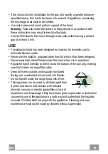
Page 16: ...es other than for which it has been designed Never leave high naked flames under the hood when it is in operation Adjust the flame intensity to direct it onto the bottom of the pan only making sure th...

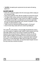
Page 17: ...usage Failure to carry out cleaning as indicated will result in a fire hazard Clean the hood using a damp cloth and a neutral liquid detergent The symbol on the product or on its packaging indicates...

Page 18: ...EN CHARACTERISTICS Dimensions 17 450 60 MIN 545 MAX 850 354 600 900 1200 422 354 422 450 600 900 1200 90 150 600 900 1200 450 60 MIN 545 MAX 850 354 422...

Page 19: ...instructions before assembling II Draw the points on the wall and drill 7 holes o AI AII Holes for the engine box support o 18 CI CII MIN165 MAX448 403 150 150 145 60 AI AII BI BIII o BI BIII Holes f...

Page 20: ...n hook to the body hood grommets and tighten into the points A A IV Secure the bracket of the pipes with the screws 3x 5x40 in BI BIII AI BI BII AII BIII CII V It is possible a security fixing using t...

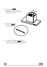
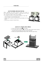
Page 21: ...t connection insert the reducer flange on the hood body outlet Fix the pipe in position using sufficient pipe clamps not sup plied Remove any activated charcoal filters 120 150 Fasten the Reducer Flan...

Page 22: ...to enable total disconnection from the mains in case of category III overvoltage as required by the installation regulations Tubes Assembly Plug a set of pipes up to overlap to the engine Upper Tube...

Page 23: ...loads turned off Motor and Light pressing and holding the button for approximately 2 seconds the remote control is disabled indicated by the LED flashing just once Pressing again the remote control is...

Page 24: ...first speed Long keypression to activate the Steam_OFF_System Decreases the working speed 3 2 1 Increases the working speed 1 2 3 Light Lights On Off Delay Function not implemented Intensive Activate...

Page 25: ...vated charcoal filter Recirculation version REPLACING THE ACTIVATED CHARCOAL FILTER The filter is not washable and cannot be regenerated and must be replaced approximately every 4 months of operation...

Page 26: ...campana extractora al conducto de humo a trav s de un tubo con un di metro m nimo de 120 mm La trayectoria del humo debe ser lo m s corta posible No conecte la campana extractora a los conductos de hu...

Page 27: ...tintos de aquellos para los que fue dise ada No deje nunca llamas altas bajo la campana cuando est en funcionamiento Ajuste la intensidad de la llama para dirigirla s lo a la parte inferior del recipi...

Page 28: ...uy frecuentemente Existe el riesgo de incendio si la limpieza no se realiza conforme a las instrucciones Limpie la campana con un pa o h medo y un detergente l quido suave El s mbolo en el producto o...

Page 29: ...ES CARACTER STICAS Dimensiones 28 450 60 MIN 545 MAX 850 354 600 900 1200 422 354 422 450 600 900 1200 90 150 600 900 1200 450 60 MIN 545 MAX 850 354 422...

Page 30: ...os trabajos de montaje II Dibuja los puntos en la pared y perfore los 7 agujeros 29 CI CII MIN165 MAX448 403 150 150 145 60 AI AII BI BIII o AI AII Agujeros de fijaci n del soporte del motor o o BI BI...

Page 31: ...tar los ojales de motor y apriete los puntos A A IV Fije el soporte de los tubos con tornillos 3x 5x40 en posici n BI BIII V se puede tener un fijaci n de seguridad en C C y atornillar 2x 5x40 desde e...

Page 32: ...si n aspirante conectar la campana al tubo de salida mediante un tubo r gido o flexible de 150 o 120 mm a discreci n del instalador Para la conexi n con el tubo de 120 mm introducir la brida de reducc...

Page 33: ...as normas que asegure la desconexi n completa de la red en las condiciones establecidas por la categor a de sobretensi n III de conformidad con las normas de instalaci n Chimenea superior Fijar a los...

Page 34: ...S est encendido el LED correspondiente se enciende Con todas las cargas apagadas Motor y Luz manteniendo pulsado el bot n durante unos 2 segundos el mando a distancia est desactivado indicato por el L...

Page 35: ...l motor a la primera velocidad Una presi n prolongada enciende el Steam_OFF_System Decrementa la velocidad de ejercicio a cada presi n 3 2 1 Incrementa la velocidad de ejercicio a cada presi n 1 2 3 L...

Page 36: ...Filtro antiolor Versi n filtrante SUSTITUCI N DEL FILTRO DE CARB N ACTIVO No se puede lavar ni regenerar se debe cambiar cada 4 meses aproximadamente o m s a menudo si su uso es muy intenso Quitar el...

Page 37: ...SO RED 1 2 1 2 ARANCIONE ORANGE ROSSO RED MOTOR 120W ROSSO RED ARANCIONE ORANGE SPEED 2 MARRONE BROWN CELESTE BLUE GIALLOVERDE YELLOWGREEN MARRONE BROWN MARRONE BROWN ROSSO RED NERO BLACK ARANCIONE OR...

Page 38: ...___________ __________________________________________________________ __________________________________________________________ __________________________________________________________ ___________...

Page 39: ......

Page 40: ...3011000048700 01 991 0487 282_01 1 1028 D003242_00...

Reviews: