


3
1. SAFETY
INFORMATION
For your safety and
correct operation of the
appliance, read this manual
carefully before installation
and use. Always keep these
instructions with the
appliance even if you move
or sell it. Users must fully
know the operation and
safety features of the
appliance.
The wire connection has
to be done by specialized
technician.
• The manufacturer will not be
held liable for any damages
resulting from incorrect or
improper installation.
• The minimum safety
distance between the cooker
top and the extractor hood
is 650 mm (some models
can be installed at a lower
height, please refer to the
paragraphs on working
dimensions and installation).
• If the instructions for
installation for the gas hob
specify a greater distance,
this must be respected.
• Check that the mains voltage
corresponds to that indicated
on the rating plate fixed to
the inside of the hood.
• Means for disconnection
must be incorporated in the
fixed wiring in accordance
with the wiring rules.
• For Class I appliances,
check that the domestic
power supply guarantees
adequate earthing.
• Connect the extractor to
the exhaust flue through a
pipe of minimum diameter
120 mm. The route of the
flue must be as short as
possible.
• Regulations concerning the
discharge of air have to be
fulfilled.
• Do not connect the extractor
hood to exhaust ducts
carrying combustion fumes
(boilers, fireplaces, etc.).
• If the extractor is used
in conjunction with non-
electrical appliances (e.g.
gas burning appliances), a
sufficient degree of aeration
must be guaranteed in the
room in order to prevent the
backflow of exhaust gas.
When the cooker hood is
used in conjunction with
appliances supplied with
energy other than electric,
the negative pressure in the
room must not exceed 0,04
mbar to prevent fumes being
drawn back into the room by
the cooker hood.
• The air must not be
discharged into a flue that is
used for exhausting fumes
from appliances burning gas
or other fuels.
EN
Summary of Contents for 110.0184.794
Page 48: ...48 1 650 I 120 RU...
Page 49: ...49 0 04 8...
Page 50: ...50 2...
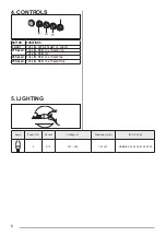
Page 51: ...51 3 4 W W 2 Z 4 L V1 V2 V3...
Page 52: ...52 5 MM ILCOS 4 E14 220 240 107 x 37 DRBB F 4 220 240 E14 35 100...
Page 65: ...65 1 650 I 120 0 04 UK...
Page 66: ...66 8...
Page 67: ...67 2 3 4 W W 2 Z...
Page 68: ...68 4 L V1 1 V2 2 V3 3 5 MM ILCOS 4 E14 220 240 107 x 37 DRBB F 4 220 240 E14 35 100...
Page 97: ...97 1 650mm 120 mm 0 04 mbar GR...
Page 98: ...98 8...
Page 99: ...99 s 2 3 4 W W 2 Z...
Page 100: ...100 4 L V1 V2 V3 5 W V mm ILCOS 4 E14 220 240 107 x 37 DRBB F 4 220 240 E14 35 100...
Page 105: ...105 1 650 I 120 0 04 mbar BG...
Page 106: ...106 8...
Page 107: ...107 2 3 4 W W 2 Z...
Page 108: ...108 4 L V1 V2 V3 B 5 W V mm ILCOS 4 E14 220 240 107 x 37 DRBB F 4 220 240 E14 35 100...
Page 109: ...109 1 650 1 120 KK...
Page 110: ...110 0 04 8...
Page 111: ...111 2 3 4 W W 2 Z...
Page 112: ...112 4 L V1 V2 V3 5 MM 4 E14 220 240 107 x 37 DRBB F 4 220 240 E14 35 100...
Page 113: ...113 1 650 mm I 120 mm 0 04 mbar MK...
Page 114: ...114 8...
Page 115: ...115 2 3 W W 2 Z...
Page 116: ...116 4 L V1 V2 V3 5 W V mm ILCOS 4 E14 220 240 107 x 37 DRBB F 4 220 240 E14 35 100...
Page 121: ...121 1 650 mm 1 120 mm SR...
Page 122: ...122 0 04 mbar 8...
Page 123: ...123 2 3 4 W W 2 Z...
Page 124: ...124 4 L V1 V2 V3 5 W V mm ILCOS 4 E14 220 240 107 x 37 DRBB F 4 220 240 E14 35 100...
Page 125: ...125 AR...
Page 126: ...126...
Page 127: ...127 Z W...
Page 129: ...129...
Page 130: ...130...
Page 131: ...131...