2016
Installation and Operation Manual
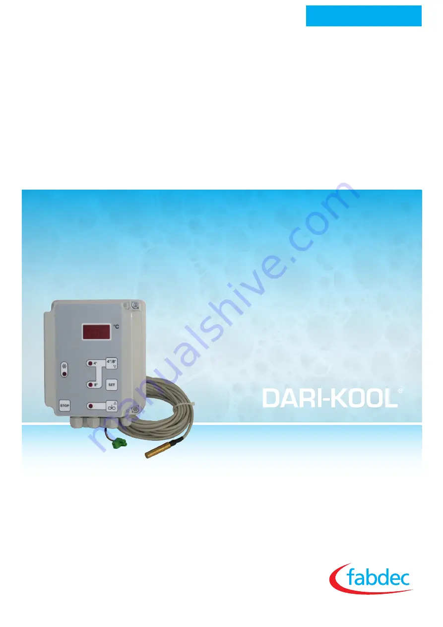
Control for milk cooling tanks COMPACT-KOOL
Page 1: ...2016 Installation and Operation Manual Control for milk cooling tanks COMPACT KOOL ...
Page 2: ...tion Page 9 Programming level operation Page 10 Configuration level operation Page 11 Intermediate stirring options during cooling Page 13 Continuous stirring in OFF mode Page 13 Setting the actual value correction Page 14 Fault indication on the display Page 14 General measures when using electronic control systems Page 15 Guarantee Page 17 Circuit diagramm without engineprotect XX 1 Page 18 Circ...
Page 3: ...y pressing a button Cooling mode Press the 4 8 button the compressor and agitator operate automati cally In between cooling periods agitator and compressor LEDs off intermediate stirring can be activated Stirring mode If stirring mode is active temperature shown in display Short intermediate stirring Briefly press the Agitator button sho appears in the display and the agitator starts to operate Lo...
Page 4: ...ice must not be installed in potentially explosive atmospheres The control cabinet for milk cooling tanks fulfils the EC requirements for electromagnetic compatibility EMC and the Low Voltage Directive LVD The safety components meet the VDE regulations Safety These operating instructions contain important technical and safety information Please read them carefully before installation and before wo...
Page 5: ...f it is necessary to shorten or lengthen the sensor cable on installation or if a sensor other than the one supplied is to be fitted the actual value correction parameter must be adjusted accordingly See the section Setting the actual value correction on page 14 Observe the permitted temperature range to which the sensor is suited Elektrical connections Sensor cable PVC Silicon temperature range C...
Page 6: ...witching contactor and motor protection switch 2 make contacts 16A AC 1 250 V 13 mm LED Display 3 digits 0 1 C 1 0 C two step controller 50 150 C 0 1 to 99 9 K free adjustable standard adjusting 0 7 K cooling see sketch IP 64 Screw terminals 20 to 70 C 0 to 50 C 75 no condensation Specifications subject to change without prior notice Sensor element Bush material Bush length Bush diameter Cable mat...
Page 7: ... of the regulator are set As subsequent interventions by the end user after the parameters have been set can result in dangerous chan ges to functions which might not be immediately obvious access to the configuration level is even more complex Operation overview The milk is cooled to the selected target temperature 4 or 8 The adjusted target temperature is displayed by LED 4 or 8 The stirrer runs...
Page 8: ...ckly Release button SET To store the changed parameter in the memory first release the arrow button and then button SET Switching back to working level possible from any parameter Press button Arrow UP and Arrow DOWN simultaneously for approx 5 seconds The current actual value appears in the display If at programming or configuration level no buttons are pressed for approx 1 minute the regulator s...
Page 9: ...rds or downwards Button Agitator in cooling mode press for appr 1 sec SHORT intermediate stirring press for appr 3 sec LONG intermediate stirringSee also the section describing the intermediate stirring options page 13 Button Agitator in OFF mode continuous stirring Press the Agitator button together with button SET in cooling mode to adjust the current target temperature upwards Button STOP therm...
Page 10: ...on after being turned off Parameter C50 Duration of SHORT intermittent stirring Duration min of stirring after short pressing of the intermittent stirring button Parameter C51 Duration of LONG intermittent stirring Duration min of stirring after longer pressing of the intermit tent stirring button Parameter C91 Sensor correction The sensor reading can be provided with a corrector which works cumul...
Page 11: ...the hysteresis is always upwards In the case of heating contacts it is below the target temperature cooling or heating contact is set at configuration level In the symmetrical hysteresis mode the value selected is distributed on both sides of the target temperature Param P20 Limit for target temperature T1 downwards Param P21 Limit for target temperature T1 upwards Param P22 Limit for target tempe...
Page 12: ...ng of minimum pause time for compressor relay contacts K1 in order to prevent repeated switching on and off Range 0 0 999 seconds Parameter P80 Switch from target temperatur T1 to T2 Setting of funktion switching target temperature 0 not possible 1 with button 2 do not use Parameter P81 Function intermittend stirring Setting of funktion start manual intermittend stirring See section Intermediate s...
Page 13: ...ediately otherwise Intermediate stirring LONG will be activated Intermediate stirring LONG Press agitator button for approx 3 secs until Lon appears in the display The duration of SHORT or LONG stirring is fixed at settings level using parameters C50 and C51 Parameter P81 is set to 2 not used Parameter P81 is set to 3 On request the control can be set for continuous stirring i e the agitator can b...
Page 14: ...r C91 Actual value correction must then be adjusted at programming level Memory fault Faulty regulator Remove the regulator and send it for repair Measurement range exceeded The maximum measurement range of the sensor has been exceeded LED Display F1 F2 F3 FFF The regulator is adjusted to the selected sensor in the factory When replacing a faulty sensor use only the same type In order to adjust th...
Page 15: ...m However in practice this is possible only with difficulty as even a normal contactor without interference suppres sion produces interference pulses of up to 3 0 kV For this reason we recommend that the following principles be taken into account during installation Try to eliminate all sources of interference by carrying out interference suppression and minimising the interference level Radio int...
Page 16: ... example be limited by using self induction diodes varistors or suppresser diodes The diagram on the left shows one possibility using a self induction diode AC voltage In the case of a c voltage interference suppression as described above is not possible Instead an RC combination must be used An RC filter must be connected as directly as possible to the inductance in order to ensure a short line I...
Page 17: ...The use of zero voltage switches is also recommended The suggestions made represent only a few of the possible ways of protecting a microprocessor controlled regulator system from interfer ence The suggested measures have the advantage that they will increase the lifetime of the devices as lower induction voltages redu ced spark formation will also reduce contact burn f Every regulator is individu...
Page 18: ... 0 1691 627200 Fax 44 0 1691 627222 Email sales fabdec com Fabdec GmbH Gerhardstrasse 5 45892 Gelsenkirchen Germany Tel 49 0 209 700 900 Fax 49 0 209 70090 20 Email germany fabdec com Fabdec LLC October Embankment 12 building 2 193091 Saint Petersburg Russia Tel 7 812 715 0102 or 7 921 977 5936 Email russia fabdec com ...