


N.C.
N.O.
C.
Fire2 Relay
Contacts
(T7)
Fire Panel (FACP) typical connection
FAAST
Fire Alarm Aspiration Sensing Technology®
FAAST
Fire Alarm Aspiration Sensing Technology®
for monitoring of device
Alarm
Short = Fire
Open = Fault
EOL
N.C.
N.O.
C.
Fire1 Relay Contacts
(T6)
Alarm
Short = Fire
Open = Fault
N.C.
N.O.
C.
Action2
Rela
y
Contacts
(T5)
Alarm
Short = Fire
Open = Fault
N.C.
N.O.
C.
Action1 Rela
y
Contacts
(T4)
Alarm
Short = Fire
Open = Fault
N.C.
N.O.
C.
Alert Relay
Contacts
(T3)
Alarm
Short = Fire
Open = Fault
N.C.
N.O.
C.
Isolate Relay
Contacts
(T10
)
Supervisory
Short = Isolate
Open = Fault
N.C.
N.O.
C.
Urgent Relay
Contacts
(T9)
Short = Urgent Fault
Open = Fault
N.C.
N.O.
C.
Minor Relay Contacts
(T8)
Short = Minor Fault
Open = Fault
N.C.
N.O.
C. (Reset)
Panel
Remote
Reset
-
-
+
Monitor
Short = Reset
Open = Fault
FACP
Supervisory
Supervisory
EOL
EOL
EOL
EOL
EOL
EOL
EOL
EOL
47K
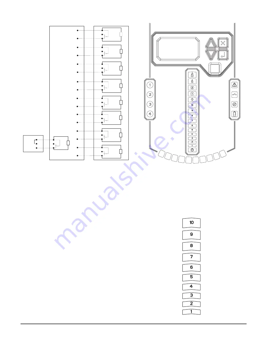
FIGURE 4. FACP WIRING DIAGRAM
FIGURE 5. USER INTERFACE DISPLAY
FIGURE 6. PARTICULATE LEVEL DISPLAY
ASP18-17
ASP118-00
ASP117-00
SYSTEM POWERING
The following procedure describes how to initially power up the FAAST system.
1. Unplug the unit’s power connector to the unit before turning on the power.
2. Turn on the power.
3. Check the voltage at the connector. Make sure it is within the re-
quired voltage range.
4. If the voltage is within the proper range, reconnect the power connec-
tor to the unit.
5. Verify the system fan starts up and air begins to flow out of the ex-
haust port. The user interface will provide the device status.
6. Connect a computer, with PipeIQ installed, to the unit using either
the USB connection on the front of the device, or the Ethernet port
located in the left side wiring door. (See the ‘Connecting to FAAST
9400X’ for detailed connection instructions.)
7. Use the PipeIQ software to set up the unit configuration required for
the particular application.
8. The PC may now be disconnected unless a permanent networked
connection is desired. (Permanent connection of RJ45 connector is
not allowed if used in a Class I, Division II hazardous location).
9. The device will establish an airflow baseline during the first five min-
utes of operation. After five minutes, the airflow level display will
provide the true measured airflow status. The device will give visual
indication of the baslining period on the LCD screen.
USER INTERFACE
The user interface, shown in Figure 5, provides the following information:
• Detector status: Normal, Alarm, General Fault, Isolate Fault, Disable
Fault, Voltage Fault
• Alarm Level: Alert, Action 1, Action 2, Fire 1, Fire 2
• Particulate Level: 1 – 10 relative to Alert
• Flow level for each pipe inlet
• LCD for device test, service, and monitoring.
PARTICULATE LEVEL DISPLAY
The particulate level display, shown in Figure 6, consists of ten amber LEDs
that correspond to the current level of the particulate level detected. The LEDs
illuminate in order from Level 1 to Level 10, starting from the bottom of the
display and moving up as the particulate level increases. Each LED represents
a 10 percent increment in the particulate level relative to the Alert level.
5 ASUG56601
firealarmresources.com