


1. Square off and de-burr the end of the sampling pipe. Ensure that the
pipe is free from any particles that might interfere with the pipe con-
nection.
2. Remove the input plug from the input port being used (either the top
or bottom of the unit).
3. Insert the air sampling pipe into the port, ensuring a snug fit.
DO NOT glue these pipes.
WIRING
WARNING
Before working on the FAAST system, notify all required authorities that the
system will be temporarily out of service. Make sure all power is removed
from the system before opening the unit. All wiring must be in accordance
with local codes.
POWER CABLES
Use the power ratings of the unit to determine the required wire sizes for each
connection. Use the power ratings of the connected products to determine the
wire size.
CONDUIT USAGE
If electrical conduit is used for system wiring, terminate the conduits at the
cable entry ports on the top or bottom of the unit, using the appropriate con-
duit connectors.
1. Run all wiring, both power and alarm, through the conduit and into
the left side of the unit enclosure, as seen in Figure 3.
2. Attach the appropriate wires to the supplied Euro connector. Follow
appropriate local codes and electrical standards for all cabling.
3. Plug the appropriate connector into the mating connector on the unit.
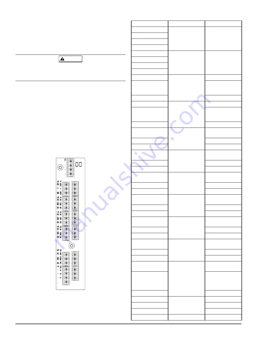
FIGURE 3. POWER AND ALARM CONNECTION BLOCK
TABLE 1. TERMINAL DESIGNATIONS
ASP114-01
CABLING REQUIREMENTS
The FAAST system provides a series of Euro style pluggable terminals, located
behind the left side door of the unit. Refer to Table 1 for the proper electrical
connections to the unit. Refer to Table 2 for a typical connection for monitor-
ing the FAAST system at a Fire Alarm Control Panel (FACP).
NAME
TERMINAL BLOCK
NOTES
External Power -
T1
Powers Aspirating
Smoke Detector
External Power -
External Power +
External Power +
SLC +
T2
Not used on
conventional models
SLC +
SLC -
SLC -
A IN
T3
RS-485 Rx
C
Rx and Tx can be
wired in a half duplex
configuration
B IN
A OUT
T4
RS-485 Tx
C
Rx and Tx can be
wired in a half duplex
configuration
B OUT
Alert NO
T5
Maintains state on loss
of power
Alert COM
Alert NC
Action 1 NO
T6
Maintains state on loss
of power
Action 1 COM
Action 1 NC
Action 2 NO
T7
Maintains state on loss
of power
Action 2 COM
Action 2 NC
Fire 1 NO
T8
Maintains state on loss
of power
Fire 1 COM
Fire 1 NC
Fire 2 NO
T9
Maintains state on loss
of power
Fire 2 COM
Fire 2 NC
Minor Fault NO
T10
Maintains state on loss
of power
Minor Fault COM
Minor Fault NC
Urgen Fault NC
T11
Always reverts to reset
on loss of power
Urgent Fault COM
NO, NC designations
are with power applied
and unit operating
without fault.
Urgent Fault NO
Isolate NO
T12
Isolate COM
Isolate NC
External Monitor
T13
4 ASUG56601
firealarmresources.com