


5
E56-6001-000
02/16/2018
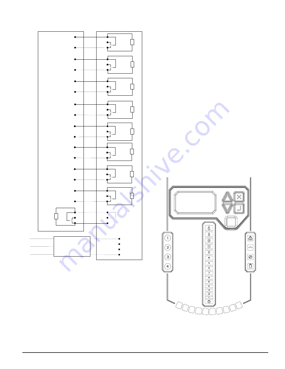
FIGURE 4. FACP WIRING DIAGRAM
N.C.
N.O.
C.
Fire Panel (FACP) typical connection
FAAST XT
for monitoring of device
Alarm
Short = Fire
Open = Fault
EOL
N.C.
N.O.
C.
Alarm
Short = Fire
Open = Fault
N.C.
N.O.
C.
Alarm
Short = Fire
Open = Fault
N.C.
N.O.
C.
Alarm
Short = Fire
Open = Fault
N.C.
N.O.
C.
Alarm
Short = Fire
Open = Fault
N.C.
N.O.
C.
Supervisory
Short = Isolate
Open = Fault
N.C.
N.O.
C.
(T
11
)
Short = Urgent Fault
Open = Fault
N.C.
N.O.
C.
(T
10
)
Short = Minor Fault
Open = Fault
FACP
Supervisory
Supervisory
EOL
EOL
EOL
EOL
EOL
EOL
EOL
External
Monitor
(T
13
)
N.C.
B.
B.
A.
N.O.
(Reset)
C.
47k
Ω
Red
Blue
EMI Line Filter
(included)
Red
Blue
Yellow (not connected)
24VDC
-
+
-
+
-
+
Panel’s
Remote
Reset
Alert
Re
la
y
C
ontacts
(T
5)
Action 1 Re
la
y
C
ontacts
(T6
)
Action 2 Re
la
y
C
ontacts
(T7
)
Fire 1 Re
la
y
C
ontacts
(T8
)
Fire 2 Re
la
y
C
ontacts
(T9
)
(T12
)
Ur
gent
Re
la
y
C
ontacts
Minor Re
la
y
C
ontacts
Isolate Re
la
y
C
ontacts
ASP136-01
SYSTEM POWERING
The following procedure describes how to initially power up the FAAST system.
1. Unplug the unit’s power connector to the unit before turning on the
power.
2. Turn on the power.
3. Check the voltage at the connector. Make sure it is within the required
voltage range.
4. If wiring is not connected to the external monitor terminal, install a 47k
Ω
resistor (provided with the unit) into the terminal block and fit it into
the T6 terminal. Remove spade connectors before installing in the wiring
terminal.
5. If the voltage is within the proper range, reconnect the power connector
to the unit.
6. Connect a computer, with PipeIQ installed, to the unit using either the
USB connection,or the Ethernet port located inside the wiring cabinet.
(See ‘Connecting to FAAST XT’ for detailed connection instructions.)
7. Use the PipeIQ software to set up the unit configuration required for the
particular application.
8. The PC may now be disconnected unless a permanent networked con-
nection is desired.
9. Verify the system fan starts up and air begins to flow out of the exhaust
port. The user interface will provide the device status.
10.
The device will establish an airflow baseline during the first five
minutes of operation after powering on, following the successful
download of a configuration to the device from PipeIQ, or after ini-
tiating Baseline Reset from Functions menu on the unit’s display.
During the initial baseline period the LCD will display Baseline message.
The calculated baseline is stored in the device’s non-volatile memory and
is used to monitor changes in the system’s airflow that may be caused
my dust build up, broken piping, clogged holes, etc. Therefore, it is im-
portant to verify that the system is setup and installed per the PipeIQ
design file and meets the requirement of the local codes and authorities.
The Baseline message is also displayed after power on reset, following
the initial baseline period. During the five minutes after power up the
device is monitoring the system to determine the current airflow baseline
of the system. Once the current airflow baseline is established, it is com-
pared to the initial baseline stored in non-volatile memory to determine
the overall health of the system.
USER INTERFACE
The user interface, shown in Figure 5, provides the following information:
• Detector status: Normal, Alarm, General Fault, Isolate Fault, Disable
Fault, Voltage Fault
• Alarm Level: Alert, Action 1, Action 2, Fire 1, Fire 2
• Particulate Level: 1 – 10 relative to Alert
• Flow level for each pipe inlet
• LCD for device test, service, and monitoring.
FIGURE 5. USER INTERFACE DISPLAY
ASP117-00
PARTICULATE LEVEL DISPLAY
The particulate level display, shown in Figure 6, consists of ten amber LEDs
that correspond to the current level of the particulate level detected. The LEDs
illuminate in order from Level 1 to Level 10, starting from the bottom of the
display and moving up as the particulate level increases. Each LED represents
a 10 percent increment in the particulate level relative to the Alert level.