background image

WARNING: If the time learning setup is done automatically then 
the slow down points are set by the board on his own

Move the leafs to the mid position

Very important for a good result

1.  Press and hold the SETUP button until the SETUP LED lights up, 

wait about 3 sec. until it turns off and  then release it imme-
diately. NOTE: If you wait too long to release it the manual 
set-up will start. The LED will blink during the setup procedure

2.  Leaf 2 (if present) starts to move slowly in closing direction, 

stopping when it reaches the mechanical stop or FCC2.

3.  Leaf 1 begins to move slowly in closing direction, stopping 

when it reaches the mechanical stop, or FCC1.

4.  Leaf 1 starts to move slowly in opening direction, followed 

by leaf 2 (if present)


still slowly

.

5.  When they both reach the open mechanical stop or FCA1 

and FCA2 they stop and reverse, leaf 2 (if present) automa-
tically starts closing at full speed followed by leaf 1.

6.  When they reach the close mechanical stop or FCC1 and 

After powering up the board for the first time or when the board 
will need it the setup LED will blink at a slow frequency to indicate 
that the setup procedure to learn the running times is needed.

The setup can be redone at any time by pressing and holding 
the setup button as indicated below. The setup cannot be done 
until the safeties and stop inputs are wired.

After the setup first movement, if the leafs are opening instead 
of closing you need to reverse the wires going to the motor that 
moves in the wrong direction  
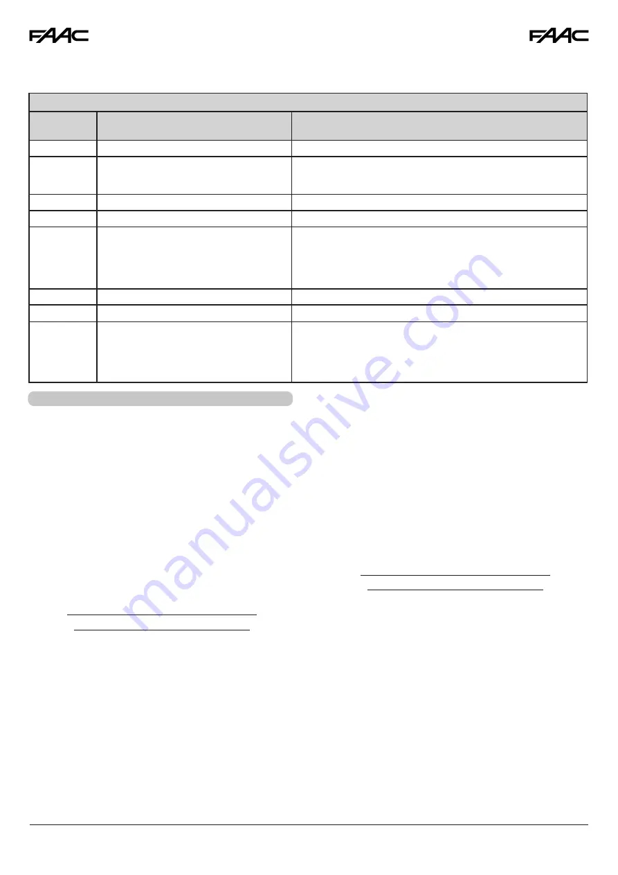
LED ERROR DISPLAY

NUMBER OF 

FLASHES

ERROR CONDITION

SOLUTION

1

OBSTACLE DETECTION

Remove the obstacle, Check force and sensitivity settings

2

BOARD IN SLEEP MODE
(Slow blinking means that the automatic open 
in case of power failure function is active)  

Verify the presence of AC power

3

MOTOR 1 FAILURE

Inspect wiring to motor. If the wiring is good replace motor 1

4

MOTOR 2 FAILURE

Inspect wiring to motor. If the wiring is good replace motor 2

5

ENCODER on motor 1 or motor 2 error

•  Verify the encoder wiring and LED status. If they are correct replace 

the encoder

•  Verify motor and encoder wire gauge are correct
•  Verify operator is not on manual and hydraulic units don’t need 

to be bled

6

FAIL SAFE FAILED

Verify the photocells wiring and alignement

7

BOARD THERMAL PROTECTION ACTIVE

Turn off the board and wait until the components cool down

8

MAX RUN TIME REACHED 
WITHOUT FINDING THE 
POSITIVE STOP (10 min. )

- Verify that the operator manual release is not engaged
- Verify that the board recognizes the mechanical stop, in case redo 
the setup procedure
- Verify that the gates slow down before reaching the positive stops. If 
they don’t then redo the setup procedure

The diagnostic LED shows only one error condition at a time, with the priority of the below table. In case there is more than 
one error once one is eliminated the LED will show the next  

FCC2 both leafs stop and leaf 1 restarts  automatically 
opening at full speed followed by leaf 2 (if present).

7.  If you selected an automatic logic the board will wait for 

the pause time and then closes the gate  automatically. 
Otherwise you have to give an OPEN command to close 
the gate. 

WARNING: If the manual time learning setup is done then the 
slow down points must be set by the installer during the proce-
dure. 

Slow down is required for proper operation.

Move the leafs to the mid position

Very important for a good result

1.  Press and hold the SETUP button until the SETUP LED lights up, 

keep it pressed for about 3 sec. until it turns off and keep it 
pressed more until the leaf 2 (if present) starts moving slowly.  
The LED will blink during the setup procedure  

2.  Leaf 2 will move in closing direction until it reaches the 

mechanical stop or FCC2

3.  Leaf 1 starts moving slowly until it reaches the mechanical 

stop or FCC1

4.  Leaf 1 starts moving in opening direction at the set speed 

(trimmer speed).

5.  At the point where you want the slowdown to start give 

an OPEN A command with the push button or the remote 
that is already stored in memory. Leaf 1 starts to slow down 
and stops when it  reaches the mechanical stop or FCA1.

6.  Leaf 2 starts moving in opening direction at the set speed 

(trimmer speed)

AUTOMATIC TIME LEARNING

MANUAL TIME LEARNING

6.  TIME LEARNING (SET-UP)

22

Summary of Contents for Safe Zone S418

Page 1: ...perator FAAC International Inc Headquarter East Coast Operations 3160 Murrell Rd Rockledge FL 32955 Tel 800 221 8278 www faacusa com FAAC International Inc West Coast Operations 357 South Acacia Avenu...

Page 2: ...ons 7 2 3 Installing The Operator 8 2 4 Wiring The Operator 10 2 5 Mechanical Stops 10 3 MANUAL OPERATION 11 3 1 Restoring Normal Operation 12 4 MAINTENANCE AND REPAIRS 12 E024U CONTROL BOARD 1 Descri...

Page 3: ...an usage Locate the gate such that persons will not come in contact with the vehi cular gate during the entire path of travel of the vehicular gate c The gate must be installed in a location so that e...

Page 4: ...ipment may reach high thermal temperatures during normal operation therefore use caution when touching the external housing of the gate operator Use the manual release mechanism according to the proce...

Page 5: ...factory or loa ding dock area or other locations not accessible by or intended to service the general public CLASS IV RESTRICTED ACCESS VEHICULAR GATE OPERATOR A vehicular gate operator or system int...

Page 6: ...s the mechanical locking of the leaf when the motor is not operating An easy to use release device allows to move the leaf in case of malfunction or a power outage The rear bracket is adjustable to gu...

Page 7: ...structure of the leaves must be sturdy and rigid suitable for an automated system There must be regular and uniform movement of the leaves with no friction or sticking along their entire movement Hing...

Page 8: ...f to 90 A B C To obtain opening of the leaf more than 90 A B C Lower A and B values produce higher peripheral leaf speeds Limit the difference between value A and value B to within 1 inches greater di...

Page 9: ...12 if the mechanical stop at closing is used or in Fig 13 if no mechanical stop at closing is used The operator could be temporarily powered with a 12Vdc battery to accomplish this 5 Secure the front...

Page 10: ...alue E may be increased see Fig 4 up to a maximum of 4 inches using appropriate spacers placed between the front bracket and the gate s leaf 11 Make all the necessary corrections and repeat the proced...

Page 11: ...Tighten the bolt The mechanical stop is coupled to a toothed section on the operator s body Fig 21 Ref 2 In case of difficulties moving the stop check that the coupling is free Do not force it If the...

Page 12: ...rm several open close operations to check that the automated system works normally NOTE During the first cycle the operator might not slow down correctly Wait for the end of the cycle and then give th...

Page 13: ...ector for the radio receiver BATTERY Connector for the backup battery J24 Jumper to disable battery charging With the jumper present the battery charger is enabled POWER SUPPLY DC Power supply input T...

Page 14: ...losing safety 5 FSW OP N C Contact for opening safety 6 GND 24 Vdc negative 7 GND 24 Vdc negative 8 24 24 Vdc positive 9 OUT 24 Vdc negative for safety TX photocell monitored 10 FCA 1 Open limit switc...

Page 15: ...e area between the opening leaves and fixed obstacles walls etc against the risk of entrapment Closing Safety Devices Are active only during the gate closing movement and are suitable for protecting t...

Page 16: ...nd closing areas against the risk of impact Typically these photocells work in combination with other monitored photocell pro tecting closing or opening entrapment zones In that case they can t be mon...

Page 17: ...t one closes During the mo vement a command stops the gate AP Automatic step by step OFF ON ON 0 4 min One command opens waits for the pause time and then closes automatically A command during the pau...

Page 18: ...PAUSE TIME ADJUSTMENT 0 4 min Turn clockwise to increase the pause time TR6 CLOSING DELAY OF LEAF 1 OVER LEAF 2 ADJUSTMENT 0 15 sec Turn clockwise to increase the delay TR1 FORCE ADJUSTMENT MOTOR 1 Tu...

Page 19: ...hen cleared ON SHADOW LOOP CONFIGURATION SW 9 Selects the behavior of the shadow loop function of the Shadow Loop or Loop Detectors Interface accessories OFF The shadow loop input is active only befor...

Page 20: ...1 10 OFF Active only for 3 sec after an open impulse from gate closed OFF Active always except 3 sec before an opening ON DS1 10 ON Indicates the gate status Active if the gate is Open or in Pause Not...

Page 21: ...sent USB key inserted and software Update in progress DON T Remove the USB key 7 LED USB1 Normal operation Number of flashes show version at power up See 10 1 BOARD MALFUNCTION ERROR POSSIBLE CAUSES S...

Page 22: ...and LED status If they are correct replace the encoder Verify motor and encoder wire gauge are correct Verify operator is not on manual and hydraulic units don t need to be bled 6 FAIL SAFE FAILED Ve...

Page 23: ...32 6 7 32 17 15 32 The E024U board is supplied on a panel that fits in a 16x14 enclosure 8 ENCLOSURE 1 Apply resistance to the gate and adjust the Force to make sure that the operator creates enough...

Page 24: ...following guidelines when installing the AC power 1 Check the local wiring codes in all cases and follow all local building codes Wiring and hookup should be performed by a qualified electrician inst...

Page 25: ...ed by FAAC otherwise the board could be damaged The E024U board keeps the operating firmware in a field pro grammable memory it can be easily upgraded through the on board USB port 11 FIRMWARE UPGRADE...

Page 26: ...t release OPEN stops saves CLOSE OPEN recloses leaves immediately 1 recloses leaves immediately no effect OPEN CLOSE disabled no effect no effect CLOSE disabled no effect OPEN CLOSE disabled CLOSING r...

Page 27: ...LOSE disabled recharges pause time CLOSE disabled CLOSING reopens leaves immediately reopens leaves immediately stops operation no effect reverses at opening see DS1 SW8 stops and opens at release OPE...

Page 28: ...disabled no effect OPEN disabled no effect CLOSE disabled no effect OPEN CLOSE disabled LOGIC C CONTINUOS COMMANDS PULSES SYSTEM STATUS OPEN A OPEN B STOP FSW OP FSW CL FSW CL OP CLOSED opens the lea...

Page 29: ...urn power back ON 9 Press and release the SW1 button quickly The board will recognize that the XIB board has been removed 10 Re program run time if needed REMOVING THE INTERFACE 1 Turn power OFF 2 Unp...

Page 30: ...en loop detector active or not connected J3 CL terminal closed loop detector in idle condition XIB board connections and second opening safety XIB board connections and only one opening safety Fig A13...

Page 31: ...EVERSE OPEN LED Turn the power on on the E024U board The LED on the inter face board will blink briefly and then will stay ON solid if the BUS connection is working correctly IMPORTANT Briefly press t...

Page 32: ...riangle Manual Release Key 2 63003356 S418 Complete Release Group 3 63000563 S418 Bodies Group 4 63002565 S418 Front and Rear Mounting Brackets 5 63003355 S418 Worm Screw Group 6 63001615 Motor S418 7...

Page 33: ...sume for them any other liability in connection with the sale or use of the products of beyond that extended herein The warranty hereinabove set forth shall not be deemed to cover maintenance parts in...

Page 34: ..._________________________________________________________ _________________________________________________________________________________________ ____________________________________________________...

Page 35: ..._________________________________________________________ _________________________________________________________________________________________ ____________________________________________________...

Page 36: ...2021 FAAC International Inc All Rights Reserved Published in Jan 2021 S418 I0806 Rev C US...

Reviews: