J355HA M50
www.FastGateOpeners.com | (800) 878-7829 | [email protected]
Page 1: ...J355HA M50 www FastGateOpeners com 800 878 7829 Sales FastGateOpeners com...
Page 2: ...currently in force 10 Beforeperforminganyoperationonthesystem disconnectthepowersupply 11 The power mains of the automation system must be fitted with a multi pole power switch with a switch contact...
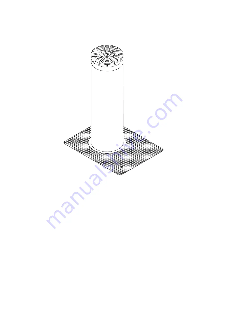
Page 3: ...ards The cylinder is moved by a hydraulic unit inside the structure 1 2 TECHNICAL DESCRIPTIONS AND SPECIFICATIONS 1 Flashing LED 2 Head 3 Cylinder 4 High position magnetic contact N C 5 Junction box 6...
Page 4: ...e C 15 55 Weight of bollard and pit kg 850 bollard 235 pit Oil quantity l 1 6 standard version 6 7 EFO version Ingress protection IP66 Size See 2 Condenser 2 70 F 400V Resistance to breakage J 3 18520...
Page 5: ...STALLATION 2 1 CONFIGURATION A flexible hose with a diameter of 100 mm should be fitted for drainage Dig the hole to a depth of approximately 1 85 m Dimensions in mm UNPROTECTED AREA IMPACT DIRECTION...
Page 6: ...instructions ENGLISH 2 2 CONSTRUCTION OF THE FOUNDATION CAGE Build the foundation cage not supplied by FAAC as shown in 4 using the 12mm and 20 mm iron rods CLASS B450C www FastGateOpeners com 800 878...
Page 7: ...lectronic board 7 Pour class C30 37 concrete around the cage to secure it properly up to about 10 cm from ground level Wait a minimum of 7 days to allow the concrete to cure properly Laythepipingneces...
Page 8: ...0 pursuant to UNI EN 12620 The bollard must only be installed once the concrete has cured for at least 7 days The compaction index of the surrounding soil should be at least 90 of the optimal Proctor...
Page 9: ...ndpassedthrough the cable guides provided on the pit sheet 8 1 and through the two corrugated conduits supplied with the pit Pass the wires through on the guides on the bollard frame as per as 8 2 the...
Page 10: ...d resting it against the coun terframe remove the two eye bolts 11 1 and fix the bollard in place using the 24 TCEI M24x50 screws supplied with the pit IMPORTANT Tighten the screws to a torque of 50Nm...
Page 11: ...rewandremovethefourTORXT30screwssecuringthecover of the hydraulic control unit in place 13 1 4 Remove the cover of the hydraulic control unit 5 Unscrewthelocknut 13 2andloosenthescrew 13 3tomove the c...
Page 12: ...pressure switch EFO solenoid valve Heater optional Refer to the diagram below EFO N O connection activtes also in case of black out EFO N C connection voluntary activation only Before performing any w...
Page 13: ...Y 7 PresstheFbuttonandholditdownwhilstsimultaneouslypressing the button to exit programming screen and save the changes made For more information on programming the equipment please refer to the relev...
Page 14: ...STOP LOOP 1 LOOP 2 LOOP 2 LOOP 1 CLOSE FSW EMERGENCY OUT 1 OUT 2 OUT 3 GND GND 24 V 24 V OUT 3 3 7 11 13 1 dF 06 LO C 3 03 Y 4 LO Cu F F F F F F F F F F 10 s F F 10 s Translation of the original instr...