


E844 3PH 19
532315 - Rev.B
Tr
ansla
tion of the orig
inal instruc
tions
ENGLISH
8
Scheduled maintenance
Operation
Frequency
Electronic equipment
Check that the power supply and connecting cables and the
cable glands are intact.
12
Check that the connectors and wiring are intact.
12
Check the integrity of the plastic board protection covers.
12
Check that there are no signs of overheating, burning etc. of
electronic components.
12
Check that the earth connections are intact.
12
Check the operation of the circuit breaker and differential
switch.
12
Control devices
Check that the installed devices and radio controls are in good
condition and that they operate correctly.
12
Sensitive edges
Check condition, fastening and correct operation.
6
Photocells
Check condition, fastening and correct operation.
6
Check the posts, ensuring that they are intact, correctly
fastened and free of deformation etc.
6
Flashing light
Check condition, fastening and correct operation.
12
Complete automation system
Check that the automation system operates correctly,
according to the set parameters, when using the various
control devices.
12
Check that the gate moves correctly - smooth, regular and
without abnormal noise.
12
Check that both the opening and closing speed are correct
and that the stop positions and slow-downs provided for
are respected.
12
Check that the manual release operates correctly: when the
release mechanism is activated, it must only be possible to
move the gate manually.
6
Check that the maximum force required for manual move-
ment of the gate is below 225 N in residential areas and 390
N in industrial or commercial settings.
6
Check that the safety edges operate correctly when faced
with an obstacle.
6
Check that each pair of photocells is working correctly.
6
Check that there is no optical/light interference between the
pairs of photocells.
6
Check the force limitation curve (standards EN 12453 and
EN 12445). For non-EU countries, of there are no specific local
regulations, the force must be less than 150 N.
6
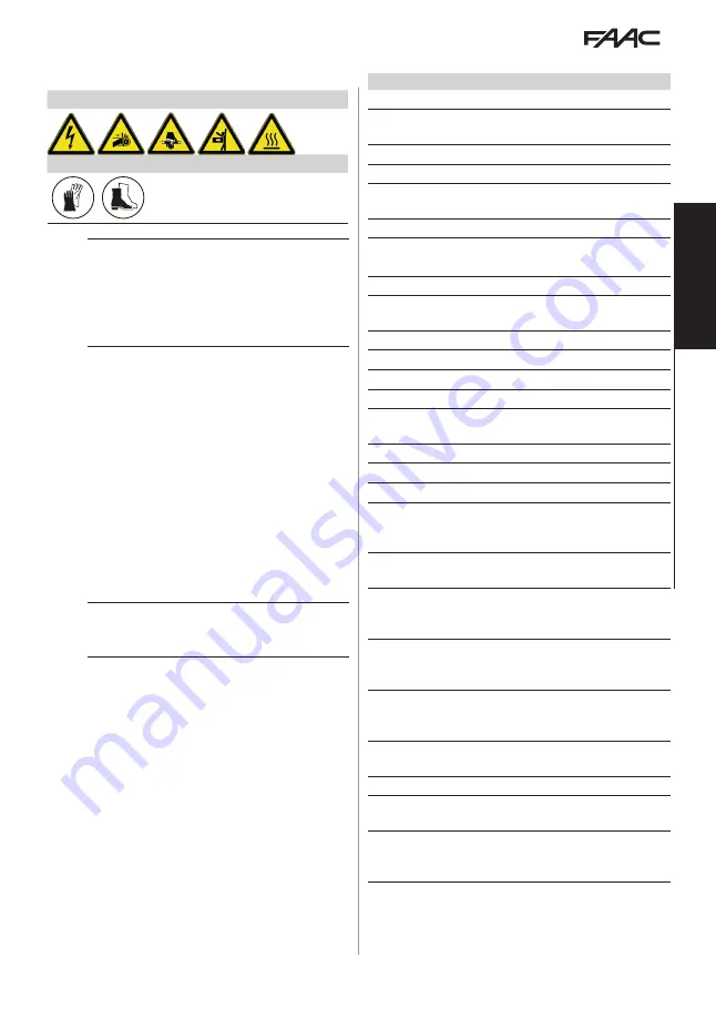
10. MAINTENANCE
RISKS
PERSONAL PROTECTIVE EQUIPMENT
F
Always shut off the power supply before performing
any maintenance operations. If the disconnect
switch is not in view, apply a warning sign stating
“WARNING - Maintenance in Progress”. Restore the
power supply only after finishing any maintenance
work and restoring the area to normal.
!
Maintenance must be performed by the installer or a
maintenance technician.
Follow all safety recommendations and instructions
given in this manual.
Mark off the work site and prohibit access/transit. Do
not leave the work site unattended.
The work area must be kept tidy and clear upon
completing maintenance.
Before starting work, wait for any hot components
to cool down.
Do not make any modifications to the original
components.
FAAC S.p.A. shall bear no liability for damage or
injury due to components that have been modified
or otherwise tampered with.
i
The warranty shall be forfeited in the event of tamper-
ing with components.
Only use original FAAC spare parts.
10.1 ROUTINE MAINTENANCE
lists the operations that should be performed
on a regular basis on the E844 3PH board in order
to keep the automation working reliably and safely;
these are given purely as a guideline and should not
be considered exhaustive. The installer/machine
manufacturer is responsible for drawing up the main-
tenance plan for the automation, supplementing this
list or modifying the maintenance operations on the
basis of the machine characteristics.


