


7
1
4
2
3
The number and selection of the electric conductors are indicated
in the drawing. The sections must be adequately increased for
lengths of over 100 meters.
Keep the control and power cables separated.
We recommend installing a pair of FAAC Fotoswitch photocells (fit
them internally, in line with the door jamb) and/or a pneumatic
safety edge (fit it on the door profile).
In the first case, use 3 cables with 0.5 mm² section for the receiver,
and 2 cables with 0.5 mm² section for the transmitter. In the second
case, install a pressure switch, with the relevant pneumatic
connection pipe and 2 cables with 0.5 mm² section.
To connect an electric lock, if any, use 2 cables with 1.5 mm
2
section.
For the connection and installation lay-outs of the control unit, for
the pulse generators, for the safety and signalling accessories, and
for the electric lock, refer to the specific instructions enclosed with
each product.
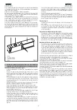
1
drive
2
by-pass valves
3
internal release
4
tank
4. TECHNICAL SPECIFICATIONS FOR THE FAAC 560 OPERATOR
AND SPECIFICATIONS FOR INSTALLING IT ON FOLDING LEAVES.
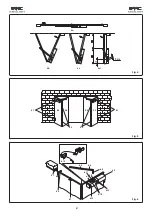
Operator installation procedure (fig. 4)
-
Install the operator on the leaf (5.3) hinged directly on a pillar
or wall.
-
Position the door as in fig. 4d; (door open). Dimension A, i.e. the
distance between the rotation axis of the operator shaft and
the rotation axis of the hinges (5.2) must be about 12 cm (MIN
6, MAX 16).
-
When you decide the position of the operator, make absolutely
sure that the by-pass valves (6.12) are always visible. To install
on right or left, overturn the operator, but always keep the
valves at the front.
-
Weld the brackets (6.10) on the top of the door in their exact
position, in order to obtain the preset dimension A.
-
Fasten the operator to the brackets with the screws (6.9).
-
Release the operator with lever 6.13 (rotating it anti-clockwise),
fit the square 6.8 - on which the arm 6.6 is already secured -
on the rotation centre (6.11).
-
Rotate the arm 6.6 in the door opening direction, until it stops
and then rotate it by 5° in the opposite direction.
-
Define the position at the mid-point of leaf 5.4 and secure, in
this position, the corner 6.7, with the pin for fastening the
telescopic arm (by Seeger ring).
-
If necessary, shorten the telescopic arm (both the elements,
sheath (6.5) and internal element (6.6) of the same quantity),
so that you can install the telescopic arm on the pin 6.7 (leave
about 5 cm between sheath and telescope end as shown in
fig. 4d).
-
Check if the door opens and closes completely and if the two
elements of the telescope remain engaged for a sufficient
distance (at least 20 cm) in the less advantageous position
(closing).
-
Grease the telescope and front pin.
-
Remove the breather screw (6.3) from the top of the operator.
Take the lever (6.13) back into the hydraulic lock position
(turning it clockwise). Locate the operator power cable and
make the electrical connections.
The door (fig. 5)
-
The door must have two or four leaves (units of two leaves for
each part).
-
They may be of any material providing the structure is rigid.
-
The hinges (5.1, 5.2) must not have too much friction or
clearance - the latter condition is essential to ensure optimum
system operation.
Top guide and sliding bearing-roller (fig. 6)
-
The door must have a top guide (6.1) (or a bottom guide)
and a roller (6.2) which, in relation to the dimensions and
weight of the leaves, must bear the leaves in addition to
guiding them, thus reducing the load on the hinges (5.1, 5.2).
-
After closure, the two leaves must always rest on a top stopping
point (6.4) of the same width as the door.
Adjustment of the by-pass valves (6.12)
-
One of the two screws adjusts closing thrust, the other screw
adjusts the opening thrust. clockwise rotations increase the
thrust, and anti-clockwise rotations reduce it. These very
sensitive valves influence the operator's pressure (thrust) and
neither do they adjust speed, nor influence the hydraulic lock.
While you restrain the door with your hands, check the thrust
supplied by the operator and then adjust in order to obtain
a sure movement, without any uncertainties.
The release system has a sprung return and, therefore, it is sufficient
to release the cable to automatically lock the operator.
A key operated lock is available for commanding the release
system from the outside (square of fig.6).
The operators without a hydraulic lock also have a manual release
to facilitate leaf movement in case of a power cut.
Figure 6 shows how to connect the key operated outside release
system (optional) by a cable to the release lever 6.13.
To release internally, fit the cable supplied in the operator package
on the release lever 6.13.
If there is not sufficient space for the operator in open position
behind the door, an installation exactly symmetrical with respect
to the one we have just described can be made: in this case,
install the operator on the more external leaf (leaves 5.4 in fig.5)
and install the corner of the pin 6.7 on the leaf which is directly
hinged on the wall or pillar (leaves 5.3 in fig.5). For the rest of the
installation, proceed as above.
Fig. 3
Summary of Contents for 560 Series
Page 1: ...560 560...


