background image

14

1

2

3

4
5
6
7

8
9

10

11

2 4  6 14 A2 

1 3  5 13 A1 

PE

COM

AP

CL

L N

19

18

OUT 4

GND

16

17

15
14

12

13

11

89

67

45

23

10

1

OPEN A

STOP

LOOP 1

LOOP 2
LOOP 2
LOOP 1

CLOSE

FSW

EMERGENCY

OUT 1

OUT 2

OUT 3

GND

GND

+24 V

+24 V

OUT 3

25

23

21

26

24

22

20

MOT1

COM

MOT2

COM
COM

LAMP

FAN

J1

NL

PE

J5

J3

A1

A1

4
5

9

10

EMERGENCY

GND

R1

12

R1

4
5

9

10

EMERGENCY

GND

R1

R1

J2

J9

230 V ~

230 V ~

230 V~

230 V~

FG7OR - 3G4

FG7OR - 16G1,5

+24V

Tr

ansla

tion of the original instruc

tions

ENGLISH

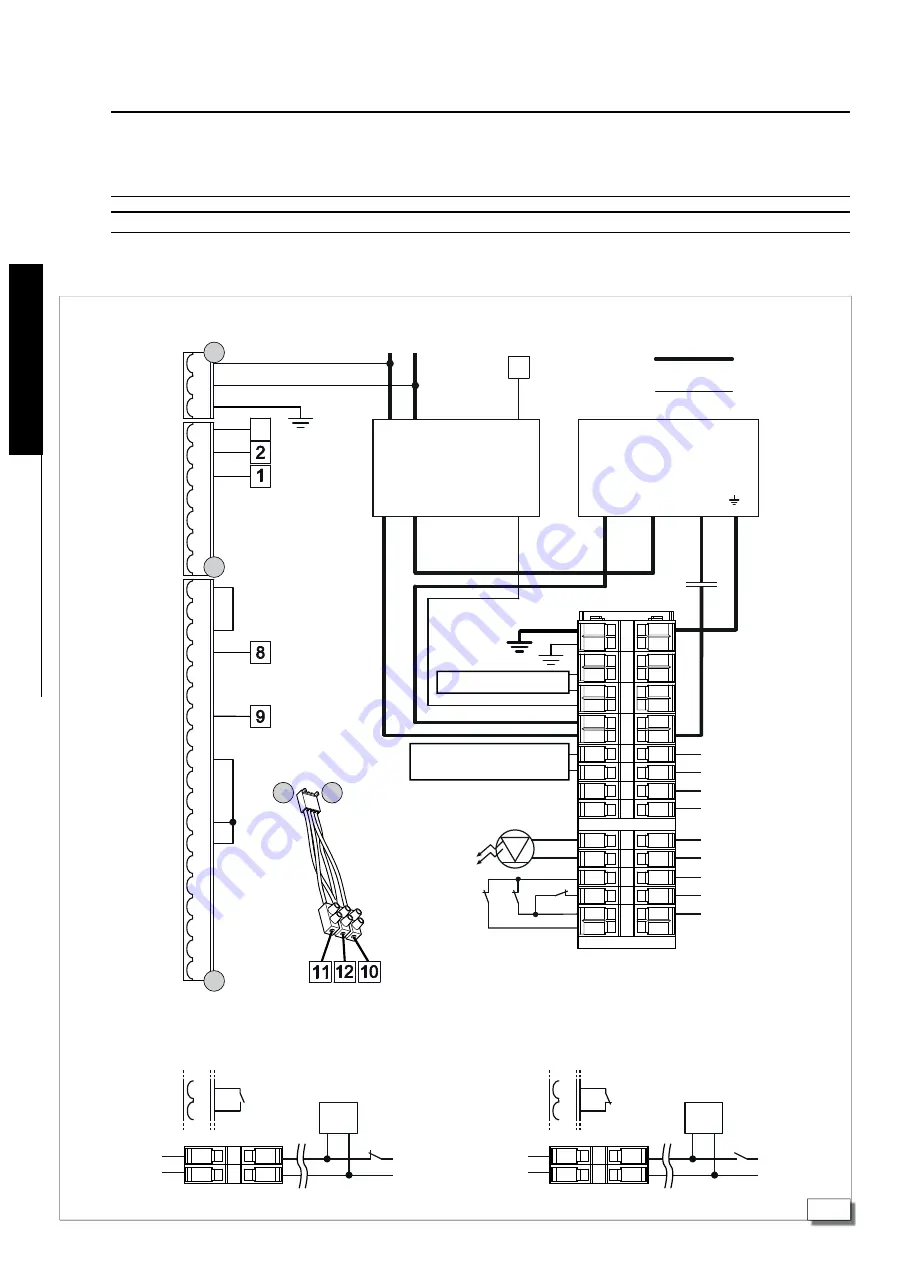
3.  ELECTRONIC EQUIPMENT JE275

BOLLARD SIDE

JE275 BOARD SIDE

Limit switch 

UP

Limit switch

DOWN

Lights

+24V

Limit switch UP
Limit switch DOWN
Limit switch common

EFO pressure 

switch

EFO

solenoid valve

Heater 

(optional)

Refer to the
diagram below

EFO N.O. connection (activtes also in case of black out)

EFO N.C. connection (voluntary activation only)

!

Before performing any work on the electronic equipment (connections, maintenance), always turn the power off.

Install a differential thermal breaker upstream with adequate tripping threshold (0.03A).

Connect the ground cable to the terminal on the J9 connector on the equipment (

14

).

Check that the mains switch is equipped with a locking key, unless this is fitted under the supervision of the operator/maintainer

The equipment must be installed at a height between 0.4 m and 2.0 m.

3.1  ELECTRICAL CONNECTIONS

Solenoid valve

Contactor

Motor

Bollard side

Bollard side

Board side

Board side

Br

ow

n

Blue

Black

www.FastGateOpeners.com  |  (800) 878-7829  |  [email protected]

Summary of Contents for 116351

Page 1: ...J355HA M50 www FastGateOpeners com 800 878 7829 Sales FastGateOpeners com ...

Page 2: ...s currently in force 10 Beforeperforminganyoperationonthesystem disconnectthepowersupply 11 The power mains of the automation system must be fitted with a multi pole power switch with a switch contact gap of at least 3 mm It is advisable to use a 6A circuit breaker with a multi pole power switch 12 Ensure there is a residual current device with a 0 03 A threshold upstream of the system 13 Checktha...

Page 3: ...ards The cylinder is moved by a hydraulic unit inside the structure 1 2 TECHNICAL DESCRIPTIONS AND SPECIFICATIONS 1 Flashing LED 2 Head 3 Cylinder 4 High position magnetic contact N C 5 Junction box 6 4 stops devices upper position 7 Oil filler plug with dipstick 8 Hydraulic control unit 9 Lowering solenoid valve 10 Cable guides 11 EFO accumulator 12 Pressure switch 13 EFO solenoid 14 Ø 100 mm hol...

Page 4: ...re C 15 55 Weight of bollard and pit kg 850 bollard 235 pit Oil quantity l 1 6 standard version 6 7 EFO version Ingress protection IP66 Size See 2 Condenser 2 70μF 400V Resistance to breakage J 3 1852000 1 Check the oil level using the dipstick positioned under the filler cap 1 7 with the piston rod fully inside and the EFO system under pressure 2 The starting capacitor 70μF 400v is pre wired insi...

Page 5: ...STALLATION 2 1 CONFIGURATION A flexible hose with a diameter of Ø100 mm should be fitted for drainage Dig the hole to a depth of approximately 1 85 m Dimensions in mm UNPROTECTED AREA IMPACT DIRECTION PROTECTED AREA Ground Excavation www FastGateOpeners com 800 878 7829 Sales FastGateOpeners com ...

Page 6: ...nstructions ENGLISH 2 2 CONSTRUCTION OF THE FOUNDATION CAGE Build the foundation cage not supplied by FAAC as shown in 4 using the Ø 12mm and Ø 20 mm iron rods CLASS B450C www FastGateOpeners com 800 878 7829 Sales FastGateOpeners com ...

Page 7: ... electronic board 7 Pour class C30 37 concrete around the cage to secure it properly up to about 10 cm from ground level Wait a minimum of 7 days to allow the concrete to cure properly Laythepipingnecessaryforconnectingthebollard thecontrolboard and any additional devices and finish the road surface with the same type of concrete N B All piping must be laid in compliance with the applicable rules ...

Page 8: ... 30 pursuant to UNI EN 12620 The bollard must only be installed once the concrete has cured for at least 7 days The compaction index of the surrounding soil should be at least 90 of the optimal Proctor curve pursuant to the UNI EN 13286 2 2005 standard The steel reinforcement complies with the B450C class ASTM A615 Grade 60 Whilst the concrete is curing insert one or more of contrast supports insi...

Page 9: ...andpassedthrough the cable guides provided on the pit sheet 8 1 and through the two corrugated conduits supplied with the pit Pass the wires through on the guides on the bollard frame as per as 8 2 then connect the corrugated conduits to the supports on the bollard frame as indicated in 8 3 Complete the electrical connections in the terminal box at the side of the bollard as shown in 14 Any additi...

Page 10: ...rd resting it against the coun terframe remove the two eye bolts 11 1 and fix the bollard in place using the 24 TCEI M24x50 screws supplied with the pit IMPORTANT Tighten the screws to a torque of 50Nm 2 6 FIXING THE TOP COVER Afterfixingthebollardinplace completetheinstallationbyposition ingandfixingthetopcoverwiththesixM8x40steelscrewsprovided Screw the two male M20 eye bolts onto the upper part...

Page 11: ...crewandremovethefourTORXT30screwssecuringthecover of the hydraulic control unit in place 13 1 4 Remove the cover of the hydraulic control unit 5 Unscrewthelocknut 13 2andloosenthescrew 13 3tomove the cylinder downwards 2 9 AUTOMATIC OPERATION To restore automatic operation 1 Turn the screw 13 4 until the stop point in order to restore automatic operation 2 Tighten the lock nut 13 5 3 Repositionthe...

Page 12: ... pressure switch EFO solenoid valve Heater optional Refer to the diagram below EFO N O connection activtes also in case of black out EFO N C connection voluntary activation only Before performing any work on the electronic equipment connections maintenance always turn the power off Install a differential thermal breaker upstream with adequate tripping threshold 0 03A Connect the ground cable to th...

Page 13: ... Y 7 PresstheFbuttonandholditdownwhilstsimultaneouslypressing the button to exit programming screen and save the changes made For more information on programming the equipment please refer to the relevant instructions 3 3 TROUBLESHOOTING Below are a series of tips to help identify and solve a number of particular issues CONDITION SUGGESTION The bollard will not rise it remains in the low position ...

Page 14: ... STOP LOOP 1 LOOP 2 LOOP 2 LOOP 1 CLOSE FSW EMERGENCY OUT 1 OUT 2 OUT 3 GND GND 24 V 24 V OUT 3 3 7 11 13 1 dF 06 LO C 3 03 Y 4 LO Cu F F F F F F F F F F 10 s F F 10 s Translation of the original instructions ENGLISH 3 4 CONNECTING SEVERAL BOLLARDS MASTER SLAVE Youcanoperatemorethanonebollardsimultaneously andthesecanbeinterconnectedusingthecorrespondingJE275deviceintheMASTER SLAVE configuration F...

Reviews: