background image

Chapter 1

1 - 10

prompts you to configure more external interfaces if you want. It is 
important to select the correct interfaces based on the way you have 
connected the cables to the back of the unit. For more information 
about interfaces, see Interfaces, following.

3. Connect the interface labeled Net2 (number 10 in Figure 1.4) to the 

network that houses the array of servers, routers, or firewalls that 
the controller load balances. 

4. If you have a hardware-based redundant system, connect the 

fail-over cable to the fail-over port on each unit (number 7 in Figure 
1.4).

5. Connect the power cable to the controller power in (number 2 in 

Figure 1.4), and then connect it to the power source. 

Interfaces

This platform can have as few as one network interface. It is helpful to 
understand interface naming conventions before you perform configuration 
tasks such as displaying interface status and settings, setting the media type, 
and setting the duplex mode. 

Interface naming conventions

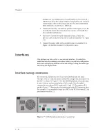
By convention, the Ethernet interfaces on the platform take the name 
<s>.<p>
, where s is the slot number of the NIC, and p is the port number on 
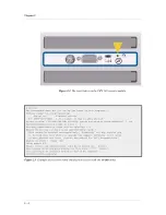
the NIC. As shown in Figure 1.7, for the 520/540 platform, slot numbering 
is top-to-bottom, and port numbering is left-to-right. Note that slot 1 
contains the two onboard NICs numbered 1.1 and 1.2. The numbers 23
and 4 in Figure 1.7 illustrate the slot numbering for the PCI expansion slots. 
For example, if you installed a single port NIC in the PCI slot marked 2, the 
port number would be 2.1.

Figure 1.7  520/540 platform slot and port numbering

Summary of Contents for 520

Page 1: ...Platform Guide 520 540 MAN 0067 00...

Page 2: ......

Page 3: ...product protected by U S Patent 6 374 300 Pending U S Patent 20020040400 Other patents pending Export Regulation Notice This product may include cryptographic software Under the Export Administration...

Page 4: ...ii...

Page 5: ...Table of Contents...

Page 6: ......

Page 7: ...ditional resources 1 18 2 Configuring the FIPS 140 Hardware Introducing FIPS 140 hardware security module support 2 1 Initializing the FIPS 140 hardware security module and creating the security world...

Page 8: ...Table of Contents iv...

Page 9: ...Reviewing the 520 540 platform Getting started Familiarizing yourself with the controller Environmental requirements Installing and connecting the hardware Interfaces Activating the license Using the...

Page 10: ......

Page 11: ...e 1 1 However there are internal differences The 540 is a dual processor platform with more memory than the 520 platform For details see Reviewing hardware specifications on page 3 1 Three PCI expansi...

Page 12: ...tenance However you must also provide standard peripheral hardware such as a keyboard or serial terminal if you want to administer the controller directly Components provided with the controller When...

Page 13: ...If you want to use the default controller configuration you must have an administrative workstation on the same IP network as the Controller You also need network hubs switches or concentrators to co...

Page 14: ...controller On the front of the unit you can turn the unit off and on or you can reset the unit You can also view the indicator lights for hard disk access Note The interfaces on every controller are...

Page 15: ...r fan failure Green Yellow or Green Flicker Green for Traffic Blink Red Out of memory or other serious condition Green Yellow or Green Flicker Green for Traffic Red One or more virtual servers have al...

Page 16: ...ard 19 inch rack To ensure safe installation and operation of the unit Install the rack according to the manufacturer s instructions and check the rack for stability before placing equipment in it Bui...

Page 17: ...le ground path maintained at all times The controller contains a lithium battery There is danger of an explosion if you replace the lithium battery incorrectly We recommend that you replace the batter...

Page 18: ...ontroller until all peripheral hardware is connected to the unit To install the hardware in a rack 1 Lift the unit into place This requires more than one person 2 Secure the unit using the four rack m...

Page 19: ...the console connect the serial cable to the terminal serial port number 6 in Figure 1 4 In this case you should not connect a keyboard to the controller If there is no keyboard connected to the contro...

Page 20: ...ce Interfaces This platform can have as few as one network interface It is helpful to understand interface naming conventions before you perform configuration tasks such as displaying interface status...

Page 21: ...e to that of the interface or to auto for auto detection If the media type is set to auto and the card does not support auto detection the default type for that interface is used for example 100BaseTX...

Page 22: ...de to full or half duplex If the media type does not allow duplex mode to be set this is indicated by an onscreen message If media type is set to auto or if setting duplex mode is not supported for th...

Page 23: ...ts the dossier to the F5 license server as well as installing the signed license certificate In order for you to use this method the unit must be installed on a network with Internet access Manual lic...

Page 24: ...License utility based on the type of BIG IP unit you are licensing If the unit does not have a license from a previouse version click License Utility to open the License Administration screen If the u...

Page 25: ...s was successful If the licensing process is not successful contact your vendor 6 You are asked to accept the End User License Agreement The system will not be fully functional until you accept this a...

Page 26: ...ative workstation open the Configuration utility using one of the following addresses https 192 168 1 245 https 192 168 245 245 These are default addresses on the unit s local area network 2 Type the...

Page 27: ...creen returns a signed license file 8 Retrieve the license file using one of the following methods Copy the entire contents of the signed license file Click Download license and save the license file...

Page 28: ...cements a list of fixes and in some cases a list of known issues Online help You can find help online in three different locations The web server on the product has PDF versions of the guides included...

Page 29: ...140 Hardware Introducing FIPS 140 hardware security module support Initializing the FIPS 140 hardware security module and creating the security world Using the key utilities to generate keys Additiona...

Page 30: ......

Page 31: ...ardware security module HSM and never leave except when in encrypted form With this HSM installed you can encrypt private keys on the 520 540 platform with a 3 DES key that resides only on the FIPS 14...

Page 32: ...single or redundant system adding another HSM to an existing security world Note You will need a paper clip or ballpoint pen and at least two of the smart cards provided with the security module three...

Page 33: ...ual is included on the Software and Documentation CD 5 Move the M O I switch to O Figure 2 1 and with the paperclip press the reset button Figure 2 2 6 Generate keys by running genconf and then genkey...

Page 34: ...Cards will be required 1 Enable future key recovery using administrator cards This cannot be enabled retrospectively Answering no may require you to discard your keys when you upgrade the support soft...

Page 35: ...tility and synchronize the configurations of the units in the redundant system This means that both 520 540 platforms in the redundant system must be synchronized in order to synchronize the SSL keys...

Page 36: ...e back of the second unit in the redundant system locate the switch labelled M O I Figure 2 1 Then using a paper clip or your fingernail move the switch to the I position 2 With the end of the ballpoi...

Page 37: ...ty world Note Connect a card reader to each of the security modules for this configuration To install both security modules and create the security world at the same time To bring two HSMs installed i...

Page 38: ...w to orient the card before inserting it in the reader The utility also prompts you to to insert the same cards into the reader attached to the second HSM to bring it into the security world at the sa...

Page 39: ...If you have done this correctly the LED blinks quickly for a moment and then blinks slowly again bigip2 sw init Key management data not yet set up at least on this computer Modules ready for re progra...

Page 40: ...the the security world you can configure the SSL Accelerator For more information see Additional configuration options on page 2 14 If this is a primary unit in a redundant system complete the tasks...

Page 41: ...authority CA to obtain a certificate gencert If you already have a key run this utility to generate a temporary certificate and request file for the SSL Accelerator WARNING After you import or generat...

Page 42: ...r certificate authority CA and follow their instructions for submitting this request form In addition to creating a request form that you can submit to a certificate authority this utility also genera...

Page 43: ...certificate applies After the utility starts it prompts you for various information After you run this utility a certificate request form is created in the following directory config bigconfig ssl cr...

Page 44: ...r options you can configure For more information see the BIG IP Reference Guide Chapter 7 SSL Accelerator Proxies All configurations have health monitoring options Refer to the BIG IP Reference Guide...

Page 45: ...3 Additional Hardware Specifications Reviewing hardware specifications 520 specifications 540 specifications...

Page 46: ......

Page 47: ...work monitoring utilities and additional contributed software SNMP gets and traps iControl API using CORBA SOAP XML Dynamic Content Support ASP active server pages VB visual basic script ActiveX JAVA...

Page 48: ...notification Specification Description Dimensions 3 5 H x 19 W x 21 7 D per unit 2U industry standard rack mount chassis Weight 26 lbs per unit Processor Single PIII 1 GHz Network Interface 2x10 100 w...

Page 49: ...re subject to change without notification Specification Description Dimensions 3 5 H x 19 W x 21 7 D per unit 2U industry standard rack mount chassis Weight 26 lbs per unit Processor Dual PIII 1 GHz N...

Page 50: ...Chapter 3 3 4...

Page 51: ...Glossary...

Page 52: ......

Page 53: ...nto IP addresses For example the domain name www sample com might translate to 101 102 103 104 dossier A dossier is an encrypted list of key platform characteristics used to identify the platform and...

Page 54: ...etup utility is available from the command line or as a web based wizard from the product splash screen SSH SSH is a protocol for secure remote login and other secure network services over a non secur...

Page 55: ...Inc Platform Guide Glossary 3 virtual server Virtual servers are a specific combination of virtual address and virtual port associated with a content site that is managed by BIG IP software or other...

Page 56: ...Glossary Glossary 4...

Page 57: ...Index...

Page 58: ......

Page 59: ...izing 2 2 installing two 2 7 M O I switch 2 3 private keys 2 1 reset button 2 4 FQDN 2 11 G gencert 2 11 genconf 2 11 genkey 2 11 Gigabit Ethernet 1 3 grounding hardware 1 7 H hardware and appearance...

Page 60: ...nd fail over cable 1 2 registration key 1 13 release notes finding 1 18 remote administration 1 3 resources finding additional 1 18 S security world creating 2 2 defined 2 2 in a redundant system 2 5...

Page 61: ......

Reviews: