background image

70


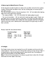
6. Balancing the Model/Control Throws  
 

At this stage the model should be in ready-to-fly condition with all of the systems 
in place including the brushless motor, servos, landing gear, the radio system, 
and battery packs.  
The recommended Center of Gravity


location is 145 - 147 mm behind the leading 

edge of the wing against the fuselage.  

For windy condition 

– 145 -147 mm behind the leading edge is good.  

For no wind condition 

– 145 mm behind the leading edge is good. Please use 

the battery pack, moving it forward or backward, to achieve the perfect balance.  
Balance the plane laterally also, holding the motor propeller shaft and a fingertip 
under the fin post, and if needed add a small weight to the light wing to make it 
track correctly.  


Please, follow the recommend throws: 

Control surface 


High rate,0 


up/left 


down/right 


Ailerons  

130 or 15 mm  

130 or 15 mm  

Elevator   110 or 13 mm  

110 or 13 mm  

Rudder  

400  

400  


9. Preflight  

 
Pre-Flight checks are just as important for any RC airplanes as they are for full 
scale airplanes. There are very much things that could go wrong during a flight. It 
is critical that you check everything twice to minimize the risk of crashing your 
expensive and carefully constructed airplane.  

Step 1. 

Check CG is set properly. It is always a good idea to check the CG each 

time before the first flight of each day.  

Summary of Contents for EUROPA PRO Mini

Page 1: ...1 F3A Europa Pro Mini Assembly manual Plane specifications Name EUROPA PRO Mini Wing span 1660 mm Lenght including spinner 1690 mm Weight empty 1100 g Weight RTF 2200 2450 g ...

Page 2: ...aircraft please make sure you have read this instruction manual several times and understood it If you have any questions please don t hesitate to contact us and before starting work make sure that the table on which the market model is to equal The contact details Email algisu555 gmail com Website http www rc composit com Good flying to you ...

Page 3: ... 3 Servos Selection 9 2 4 Radio Selection 9 3 Warranty Information 10 4 Model Assembly Process 11 4 1 Fuselage 11 4 2 Wings 39 4 3 Stabs 57 4 4 Ruder 63 5 Control Horn Installation 66 5 1 Aileron control horn installation 66 5 2 Elevator control horn installation 67 5 3 Ruder and ruder control horn installation 68 6 Balancing the Model Control Throws 70 7 Preflight 70 ...

Page 4: ...lways wear safety goggles a particle mask and rubber gloves when grinding drilling and sanding this parts Vacuum the parts and the work area thoroughly after working with fiberglass and carbon fiber parts It is important to understand that RC Composit Company is unable to monitor whether you follow the instructions contained in this instruction manual regarding the construction operation and maint...

Page 5: ...plywood version KIT 1 Laser cut plywoods parts 2 Laser cut balsa parts 3 Laser cut balsa covering for fuselage wings stabs rudder 4 Wings tubes 5 Composite parts canopy motor mounting lower hood 6 Komposite landing geer 7 Bolts nuts weel axses wheels wheelpants ...

Page 6: ...t will blow back into your eyes Always wear safety goggles or safety shield a particle mask and rubber gloves when grinding drilling and sanding this parts Wear safety goggles or safety shield Wear particle mask Wear rubber gloves Vacuum the parts and the work area thoroughly after working with fiberglass and carbon fiber parts Tools Felt tip Marker or Pencil Sander Ruler Metric and Standard Cours...

Page 7: ...ives 15 and 30 Minute Epoxy Thick CA cyanoacrylate glue Masking Tape Double Sided Tape Epoxy filler Thread Locker Acetone Alcohol swabs or Rubbing alcohol Paper or plastic caps Wooden coffee spoons Cotton buds ...

Page 8: ...ciency and highest performance reached with RTF weight 2450 grams AT 4120 KV 550 model brushless motor Speed controller 70 A or Castle Creations 80 PT model 16 x 10 E Carbon Propeller One 1 6 S 40C 3600 4000 mAh LiPo pack or two 2 3 S 40C 3600 4000 mAh LiPos ...

Page 9: ...cm Rudder one 1 Digital Servo 4 5 kg cm Make sure you use same or equivalent torque servos that are digital Please do not risk your plane by using low torque or analog servos Using of weak servos will increase chance of flutter and will reduce the accuracy of the airplane flight 2 4 Radio Selection For Europa PRO Mini we recommend use minimum 6 channel 2 4 GHz computer radio system ...

Page 10: ...h the model parts within 30 days of receiving your airplane KIT to be covered under warranty If you wish to return this aircraft for any reason a 20 restock fee will be charged to the customer In addition the customer is responsible for all return shipping cost and all prior shipping cost will not be refunded Parts will be exchanged or replaced once the original item is returned at the owner s exp...

Page 11: ...11 4 Model Assembly Process 4 1 Fuselage ...

Page 12: ...12 ...

Page 13: ...13 ...

Page 14: ...14 ...

Page 15: ...15 ...

Page 16: ...16 ...

Page 17: ...17 ...

Page 18: ...18 ...

Page 19: ...19 ...

Page 20: ...20 ...

Page 21: ...21 ...

Page 22: ...22 ...

Page 23: ...23 ...

Page 24: ...24 ...

Page 25: ...25 ...

Page 26: ...26 ...

Page 27: ...27 ...

Page 28: ...28 ...

Page 29: ...29 WARNING Before applying fuzelage balza all parts assembled PVA glue ...

Page 30: ...30 ...

Page 31: ...31 ...

Page 32: ...32 WARNING one edge balza glued CA glue ...

Page 33: ...33 ...

Page 34: ...34 ...

Page 35: ...35 ...

Page 36: ...36 ...

Page 37: ...37 WARNING Do not forget to paste the details of the hinge ...

Page 38: ...38 ...

Page 39: ...39 4 2 Wings ...

Page 40: ...40 ...

Page 41: ...41 ...

Page 42: ...42 ...

Page 43: ...43 Warning the front edge of the sand ...

Page 44: ...44 Warning First glue the lower wing half Warning first rear edge glued with CA glue and pressed ...

Page 45: ...45 ...

Page 46: ...46 ...

Page 47: ...47 Warning 2 mm tape stuck on the support rib neu WING Warning PVA glue stained rib ...

Page 48: ...48 Warning PVA glue stained lacings and wait 0 5 hours until the glue feel Warning put a hot iron cladding and heat all the places ...

Page 49: ...49 ...

Page 50: ...50 ...

Page 51: ...51 ...

Page 52: ...52 ...

Page 53: ...53 ...

Page 54: ...54 Warning ailerons cut and glue the balsą strips of sand at an angle of 45 degrees ...

Page 55: ...55 ...

Page 56: ...56 ...

Page 57: ...57 4 3 Stabs ...

Page 58: ...58 ...

Page 59: ...59 ...

Page 60: ...60 ...

Page 61: ...61 ...

Page 62: ...62 ...

Page 63: ...63 4 4 Ruder ...

Page 64: ...64 ...

Page 65: ...65 ...

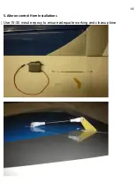
Page 66: ...66 5 Aileron control Horn Installations Use 15 30 minute epoxy to ensure adequate working and cleanup time ...

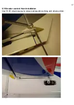
Page 67: ...67 5 1 Elevator control Horn Installation Use 15 30 minute epoxy to ensure adequate working and cleanup time ...

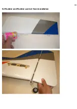
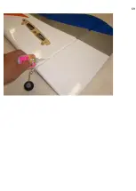
Page 68: ...68 5 2 Rudder and Rudder control Horn Installation ...

Page 69: ...69 ...

Page 70: ... plane laterally also holding the motor propeller shaft and a fingertip under the fin post and if needed add a small weight to the light wing to make it track correctly Please follow the recommend throws Control surface High rate 0 up left down right Ailerons 130 or 15 mm 130 or 15 mm Elevator 110 or 13 mm 110 or 13 mm Rudder 400 400 9 Preflight Pre Flight checks are just as important for any RC a...

Page 71: ... are free from binding and are centered Check that all hinges are tight and will not pull out Control linkages must be rigid and tight and have no slop Step 6 The engine vibrations during flight sometimes cause bolts to vibrate loose Make sure the bolts holding the wing to the fuselage are in place and are tight Make sure all engine mounting bolts and servo screws are tight Also make sure the prop...

Reviews: