background image

This equipment should be installed and operated with a minimum distance 20cm between the 
radiator and your body.

EU Conformity Statement
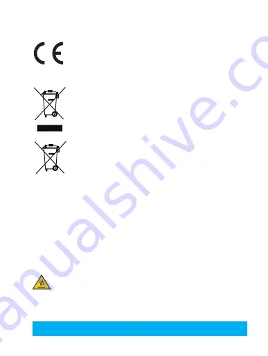
This product and - if applicable - the supplied accessories too are marked with "CE" 
and comply therefore with the applicable harmonized European standards listed under 
the Radio Equipment Directive 2014/53/EU, the EMC Directive 2014/30/EU, the RoHS 
Directive 2011/65/EU.
2012/19/EU (WEEE directive): Products marked with this symbol cannot be disposed 
of as unsorted municipal waste in the European Union. For proper recycling, return 
this product to your local supplier upon the purchase of equivalent new equipment, 
or dispose of it at designated collection points. For more information see: www.
recyclethis.info. 

2006/66/EC and its amendment 2013/56/EU (battery directive): This product contains 
a battery that cannot be disposed of as unsorted municipal waste in the European 
Union. See the product documentation for specific battery information. The battery is 
marked with this symbol, which may include lettering to indicate cadmium (Cd), lead 
(Pb), or mercury (Hg). For proper recycling, return the battery to your supplier or to a 
designated collection point. For more information see: www.recyclethis.info.

EC DECLARATION OF CONFORMITY

Hereby, Hangzhou Hikvision Digital Technology Co., Ltd. declares that the radio equipment type 
[CS-CV228, CS-CV226, CS-CV220, CS-CV320, CS-CV326, CS-CV328, CS-CV420, CS-CV426, CS-
CV428] is in compliance with Directive 2014/53/EU.
The full text of the EC DECLARATION OF CONFORMITY is available at the following web link:
http://www.ezvizlife.com/declaration-of-conformity.

Safety Instruction

*90: THE EQUIPMENT FOR RESTRICTED ACCESS LOCATIONS, AND OUTER SURFACE OF PRODUCT HAVE 

 OR 

WARNING

HOT SURFACE

DO NOT TOUCH

 MARKING.

Due to the product shape and dimension, the name and address of the 
importer/manufacturer are printed on the package.

SAVE THIS MANUAL FOR FUTURE REFERENCE

Summary of Contents for CS-CV220

Page 1: ...www ezvizlife com...

Page 2: ......

Page 3: ...O THE MAXIMUM EXTENT PERMITTED BY APPLICABLE LAW THE PRODUCT DESCRIBED WITH ITS HARDWARE SOFTWARE AND FIRMWARE IS PROVIDED AS IS WITH ALL FAULTS AND ERRORS AND HIKVISION MAKES NO WARRANTIES EXPRESS OR...

Page 4: ...may not cause harmful interference and 2 This device must accept any interference received including interference that may cause undesired operation Please take attention that changes or modification...

Page 5: ...of as unsorted municipal waste in the European Union See the product documentation for specific battery information The battery is marked with this symbol which may include lettering to indicate cadmi...

Page 6: ...6 Camera x1 Power Adapter x1 Drill Template x1 Base x1 Screw Kit x1 Waterproof Kit x1 Quick Start Guide x1 Basics LED Indicator Inside IR Light Lens Box Content...

Page 7: ...starting up Slowly Flashing Red Wi Fi connection has failed Fastly Flashing Red Device exception e g MicroSD card error Solid Blue Video is being viewed or played back in EZVIZ App Flastly Flashing B...

Page 8: ...r on Option 1 Power on the device by connecting to the power outlet by a power cable Option 2 Power on the device by PoE switch Purchased Separately Option 1 Power Outlet Power Cable Option 2 PoE Swit...

Page 9: ...an EZVIZ user account following the start up wizard 2 Add a camera to EZVIZ Log into the EZVIZ app In the Home screen tap on the upper right corner to continue Scan the QR Code on the cover of this m...

Page 10: ...g 1 Install the mounting template Place drill template onto the surface you have chosen to mount the camera For the cement wall ceiling only Drill screw holes according to the template and insert thre...

Page 11: ...nstall the Camera Mount the camera to the mounting plate Turn it clockwise until it is fixed For side wiring Rotate camera as shown in the figure 2 1 For top wiring 2 1 Rotate camera as shown in the f...

Page 12: ...etwork cable A Put the A side through the gasket and the encap Connect a new network plug with the cable A Insert the gasket to the network interface Insert the network plug into the network interface...

Page 13: ...4 Adjusting the Surveillance Angle 2 1 4 3 Loosen the rotary knob Adjust angle Tighten the rotary knob Turn the camera as shown in the figure For detailed information please refer to www ezvizlife co...

Reviews: