ELECTRICAL COMPONENTS & WIRING
Page K-7
Repair and Service Manual
Read all of Section B and this section before attempting any procedure. Pay particular attention to all Notes, Cautions and Warnings.
B
B
1. Disconnect the battery cable at the negative (-), BL-,
battery terminal using an insulated wrench.
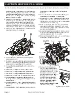
2. Remove two Torx head screws securing the controller
splash shield to the rear body, then remove the christ-
mas tree rivet securing the splash shield to the con-
troller, raise the splash shield and turn it over to
expose the reverse warning indicator and wires.
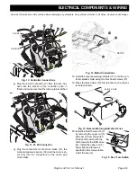
3. Remove the two torx head screws (5) securing the
reverse warning indicator (4) to the splash shield.
4. Cut the wires close to the reverse warning indicator
(4).
5. Strip insulation from the end of each wire, using a butt
splice connector and heat shrink tubing connect the
wires from the replacement reverse warning indicator
(4) to the wire harness.
6. Secure the new reverse warning indicator (4) to the
splash shield with the torx head screws (5).
7. Reinstall the splash shield.
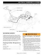
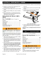
Fig. 18 Reverse Warning Indicator
ITEM
TORQUE SPECIFICATION
5
12- 15 in. lbs (1.3 - 1.7 Nm)
Splash Shield

