


2. Installation
A. When installing this chamber, please avoid placing it in any area where corrosive gas or
explosive gas is present. It is also highly recommended that the area be as dust free as
possible with controlled humidity.
B. The chamber should be placed as close to the mains power source (power transformer)
and mains breaker as possible.
C. Due to the heat generated by the solar array, keep flammable materials away from the
top of the chamber.
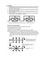
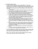
D. Please refer to the following diagrams to ensure proper clearance around the chamber
for proper operation and maintenance / inspection
Electrical / Power Characteristics
System Power: 3 Ø; 208V AC; 60Hz; 35kVA (approximately 100 A)
Cooling Blower Fans: 0.75 kW × 2 units
Solar Lamps: 208V; 400W × 60 lamps
Irradiation Power Control: 1500W solar lamp control circuit (approximately 3 A)
Mains Power Connection: 3 Ø; 4 – wire; RED, WHITE, BLACK power phase connections
and GREEN ground connection; single phase solar lamp circuits are equally divided to
balance the power over all three phases. To protect against unbalanced or open phase
power failures, the system uses a voltage detecting (APR-S) phase reversal power
breaker.
Overhead View
Frontal View
Rear
Side
Side
Top
600mm (24 in)
600mm (24 in)
600mm
(24 i )
600mm
(24 i )
600mm
(24 i )
600mm
(24 i )
This spacing is required for proper operation and routine inspection / maintenance
Chamber Power
Connections
Mains Power
Green
Black
White
Red
Black
White
Red
Green
Black
White
Red
Black
White
Red
Chamber Power
Connections
Mains Power
Alternative mains power phase
connections.
Normal electrical connection. If system does not
function it may be due to phase connection
mismatch with (APR-S) breaker. Please
reconnect mains power as illustrated below.
Electrical safety is provided through a dedicated earth
connection. It is vital to ensure that the system is
connected to earth ground.
Alternative
connections


