


2
XTP SFR HD 4K • Setup Guide (Continued)
Connection Details
RS-232 and IR Over XTP Wiring
To pass bidirectional serial command signals between XTP-compatible devices, connect
a control device to the three leftmost poles (Tx, Rx, and G) of the 5-pole captive screw
connector. To transmit and receive IR signals, connect a control device to the three rightmost
poles (G, Tx, and Rx).
NOTE:
RS-232 and IR data can be transmitted and received simultaneously.
Audio Wiring
Wire the audio output connector as
shown to the right. Use the supplied
tie wrap to strap the audio cable to the
extended tail of the connector.
ATTENTION:
For unbalanced audio, connect the sleeves to the ground contact. DO NOT connect the sleeves to the
negative (–) contacts.
ATTENTION :
Pour l’audio asymétrique, connectez les manchons au contact au sol. Ne PAS connecter les manchons aux
contacts négatifs (–).
NOTE:
The length of exposed wires is critical. The ideal length is 3/16 inch (5 mm).
Operation
After all transmitters and connected devices are connected and powered on, the system is fully operational. If any issues arise,
verify that the cables are routed and connected properly.
NOTE:
Use the Extron XTP System Configuration Software or Simple Instruction Set (SIS) commands to configure the scaler
(see the
XTP SFR HD 4K User Guide
on the Extron website).
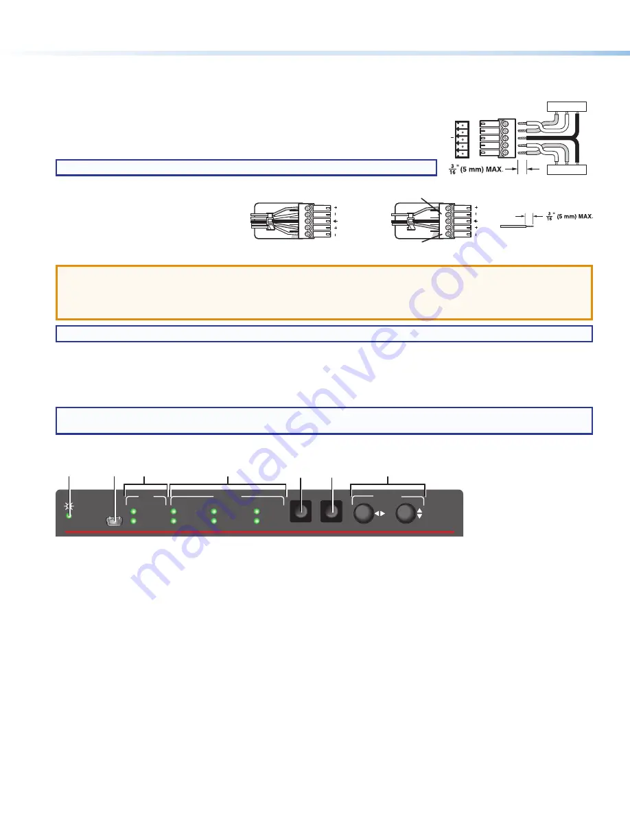
Front Panel Overview
XTP SFR HD 4K
SIGNAL
ADJUST
Extron
HDCP
HBR
HDMI
BITSTREAM
S/PDIF
LPCM
MENU
ENTER
ANALOG
CONFIG
AUDIO
XTP
B
A
C
D
E
F
G
Figure 2.
Front Panel Features
A
Power LED indicator
— Lights on the front and rear panels when power is applied to the device.
B
Configuration port
— Connect a host device to the USB mini-B port for device configuration, control, and firmware upgrades.
C
XTP LED indicators
Signal LED
— Lights when an active XTP video signal is received.
HDCP LED
— Lights when the XTP input signal is encrypted.
D
Audio LED indicators
HBR LED
— Lights when the embedded audio signal is high bit rate audio.
Bitstream LED
— Lights when the embedded audio input signal is Dolby Digital, DTS audio format, and 2-ch Dolby.
LPCM LED
— Lights when the embedded audio input signal is 2-channel LPCM.
HDMI LED
— Lights when HDMI embedded audio output (HBR, bitstream, or LPCM) is enabled.
S/PDIF LED
— Lights when S/PDIF audio output (multi-channel or LPCM) is enabled.
Analog LED
— Lights when analog audio output is enabled.
E
Menu button
— Press this button to access and navigate the on-screen display (OSD) menu system.
F
Enter button
— Press this button to select submenus and submenu items.
G
Adjustment knobs
— Rotate the horizontal and vertical knobs to navigate the on-screen display menu and to adjust settings.
Tx/Rx
Pins
Rx
Tx
RS-23
2
Rx
Tx
Tx
Rx
Rx
Tx
IR Device
RS-232 Device
G
G
G
IR
Do not tin
the wires!
Balanced Audio Output
Tip
Ring
Tip
Ring
Sleeves
Unbalanced Audio Output
Tip
No Ground Here
No Ground Here
Tip
Sleeves
LR
LR


