background image

TP Receivers • Specifications, Accessories, and Part Numbers


A-3

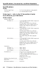
Audio

Number/signal type .....................  1 or 2 sets of analog proprietary signals
Connectors .....................................  1 or 2 shielded RJ-45 female
Frequency response ......................  20 Hz to 20 kHz, >±0.05 dB
THD + Noise ..................................  0.03% @ 1 kHz, 0.3% @ 20 kHz at 

maximum output (unweighted)

S/N ..................................................  >63 dB at nominal level
Crosstalk .........................................  <-80 dB @ 1 kHz, fully loaded
Stereo channel separation ............  >80 dB @ 1 kHz
CMRR ..............................................  >33 dB @ 20 Hz to 20 kHz

Audio input — refer to the TP Transmitters Family 

User’s Manual, part #68-546-02

0 dBu = 0.775 Vrms, 0 dBV = 1 Vrms, 0 dBV 

 2 dBu

Audio output

Number/signal type

TP R BNC A ........................  1 stereo audio balanced/unbalanced, and 

1 stereo audio unbalanced

TP R 15HD A ......................  1 stereo audio balanced/unbalanced
TP R BNC AV .....................  2 stereo audio balanced/unbalanced, and 

2 stereo audio unbalanced

Connectors

TP R 15HD A ......................  (1) 3.5 mm, 5-pole captive screw connector 

per input

All other models ................  2 female RCA (left/right) per input

(1) 3.5 mm, 5-pole captive screw connector 

per input

Impedance ......................................  50 ohms unbalanced, 100 ohms balanced
Gain error .......................................  ±0.1 dB channel to channel
Maximum level (600 ohm) ...........  >+11.5 dBm, balanced at 1%THD+N

General

Power (TP R BNC AV) ..................  100 VAC to 240 VAC, 50-60 Hz, 40 watts, 

internal

External power supply (all models except TP R BNC AV) 

100 VAC to 240 VAC, 50-60 Hz, external; to 

15 VDC, 0.8 A, regulated

Power input requirements

TP R BNC A  .......................  15 VDC, 0.3 A (minimum)
TP R 15HD A ......................  15 VDC, 0.34 A (maximum) 

Summary of Contents for TP R BNC A

Page 1: ...HIgh Resolution Video Composite Video and Stereo Audio Twisted Pair Cable Transmission Products TP Receivers Family C Do not connect this device to a computer data or telecommunications network 68 547 02 Rev J 01 09 ...

Page 2: ...faufmerksam machen daß im Inneren des Gehäuses dieses ProduktesgefährlicheSpannungen dienichtisoliert sind und die einen elektrischen Schock verursachen können herrschen Achtung Lesen der Anleitungen Bevor Sie das Gerät zum ersten Mal verwenden sollten Sie alle Sicherheits und Bedienungsanleitungen genau durchlesen und verstehen Aufbewahren der Anleitungen Die Hinweise zur elektrischen Sicherheit ...

Page 3: ...rt 15 of the FCC Rules Operation is subject to the following two conditions 1 this device may not cause harmful interference and 2 this device must accept any interference received including interference that may cause undesired operation The Class A limits are designed to provide reasonable protection against harmful interference when the equipment is operated in a commercial environment This equ...

Page 4: ...ii TP Receivers ...

Page 5: ... receiver 2 7 Rack mounting TP R BNC A TP R BNC AV TP R 15HD A 2 8 Furniture mounting 2 9 Projector mounting 2 11 Rear panel features and cabling 2 12 Transmitted signal cabling 2 12 Output cabling 2 13 Computer video 2 13 Composite video 2 14 Audio 2 15 Power connector 2 15 Termination of TP cable 2 16 Cable testing 2 17 Equalizing pair skew 2 17 Front Panel Controls and Indicators 2 19 Troublesh...

Page 6: ... cont d 68 547 02 Rev J 01 09 All trademarks mentioned in this manual are the properties of their respective owners Appendix Specifications Accessories and Part Numbers A 1 Specifications A 2 Included Parts A 6 Extron Accessories A 6 Cables Adapters A 7 ...

Page 7: ...TP Receivers 1 Chapter One Introduction About the TP Receivers Features ...

Page 8: ...ing table specifies recommended maximum transmission distances using Extron Enhanced Skew Free A V UTP cable or UTP CAT 5 cable terminated with CAT 6 or at least CAT 5e rated connectors N Extron recommends using the highest quality pre terminated and tested cable Cables terminated on site should be tested to ensure compliance with Category 5e specifications Recommended transmission ranges at 60 Hz...

Page 9: ... on 3 5 mm 5 pole captive screw connectors Level control Allows manual control of image brightness Peaking control Allows manual control of image sharpness TP R BNC A receiver The TP R BNC A receiver has the following features Video output Provides RGBHV RGBS or RGsB video on 5 BNC connectors RJ 45 connector Allows attachment to an Extron TP transmitter Cable length compensation Compensates for lo...

Page 10: ...s for computer input and one is for A V input Cable length compensation Allows you to select whether to compensate for long cable runs automatically or manually Mounting Mounts in a rack with an Extron 1U Universal Rack Shelf Kit part 60 190 01 or 1U Basic Rack Shelf part 60 604 02 Mounts to a projector mounting bracket with the Extron Pole Mount Kit PMK 200 part 70 077 04 Mounts under or through ...

Page 11: ...deo S video or composite video RJ 45 connector Allows attachment to an Extron TP transmitter Mounting Mounts in an Extron VersaToolsTM 1U Rack Shelf part 60 190 20 VersaTools 1U Basic Rack Shelf part 60 604 20 a standard Universal 1U Universal Rack Shelf Kit part 60 190 01 or 1U Basic Rack Shelf part 60 604 02 Mounts under furniture or to a projector bracket with Extron s optional mounting kits pa...

Page 12: ...TP Receivers Introduction Introduction cont d 1 6 This page intentionally left blank ...

Page 13: ...TP Receivers 2 Chapter Two Installation and Operation Installation Overview Front Panel Controls and Indicators Troubleshooting ...

Page 14: ...he composite video TP link to work with the similarly redesigned TP T 15HD AV transmitter or with older unmodified transmitters Redesigned receivers and transmitters have an identifying label 4 Mount the receiver in a rack the TP R 15HD A can be mounted in a standard rack or in a VersaTools rack under a desk or podium in a desk or table all except TP R 15HD A or on a projector bracket See Mounting...

Page 15: ...ly may not be necessary in some applications Use the following guidelines The TP T 15HD A and TP T 15HD AV may not require a local power supply for cable lengths of 300 feet or less All of the following transmitters require the local power supply TP T BNC DA4 TP T 15HD 45 TP T A 45 VTT001 Any transmitter connected to a TP R 15HD A If problems are encountered such as a missing or poor quality image...

Page 16: ... U25 Component S video Composite J3 1 2 3 J3 RGB OUTP UT RGB INPUT A V INPUT A V OUTP UT AUDIO R VIDEO G B H HV V A AUDIO L R B A L R B ISOG C SYNC 50 60 Hz 10 0 2 40 V 1 3 A Lift Cover Straight Up TP R BNC AV Remove 8 Screws Remove 5 TP R BNC A or 6 TP R BNC AV BNC Hex Nuts Figure 2 1 Video jumper configuration 2 Using an Extron BNC extraction tool part 100 096 01 or a 14 mm deep well socket with...

Page 17: ...esigned modified receivers and transmitters are fully compatible with each other and with the TPX 88 A Most can also be jumpered to be compatible with the older unmodified transmitters and receivers but not the TPX 88 A The TP T A 45 incorporates the redesigned audio circuits but cannot be jumpered for backwards compatibility N Most redesigned modified receivers and transmitters have an identifyin...

Page 18: ... 1 Figure 2 2 Audio jumper configuration 2 Using an Extron BNC extraction tool part 100 096 01 or a 14 mm deep well socket with thin walls remove the five or six hex nuts securing the BNC connectors to the rear panel 3 Slide the cover to the rear until the cover clears the BNC connectors then lift the cover off 4 Locate J10 and J11 on the composite video printed circuit board See figure 2 2 a For ...

Page 19: ...C specified by Extron 2 Reduced air flow Install the equipment in the rack so that the equipment gets adequate air flow for safe operation 3 Mechanical loading Mount the equipment in the rack so that uneven mechanical loading does not create a hazardous condition 4 Circuit overloading Connect the equipment to the supply circuit and consider the effect that circuit overloading might have on overcur...

Page 20: ... 190 01 figure 2 3 The TP R BNC A and TP R BNC AV mount on the left or right side of the rack The TP R 15HD A mounts in one of eight locations on the rack TP R 15 HD A RGB PE AKING LE VE L TP R 15 HD A RGB PE AKING LE VE L TP R 15 HD A RGB PE AKING LE VE L TP R BNC AV VIDE O MA NU AL AU TO LE VE L PE AK ING RG B MA NU AL AU TO LE VE L PE AK ING 2 4 40 x 3 16 Screws Use 2 Mounting Holes on Opposite...

Page 21: ...em 2 Mount the receiver on the rack shelf using two 4 40 x 3 16 screws in opposite diagonal corners to secure the receiver to the shelf 3 Install blank panel s included in the 1U universal and VersaTools rack kits optional for the 1U basic rack kit or other unit s to the rack shelf N Only the TP R 15HD A and products in the Extron VersaTools line can be mounted on a VersaTools shelf Any 1U rack mo...

Page 22: ...ounted Under desk Mounted TP R 15HD A RGB PEAKING LE VEL Figure 2 5 Under desk or through desk mounting 2 For through surface mounting all except TP R 15HD A cut the proper sized hole in the mounting surface 3 Hold the receiver with the attached brackets against the underside of the table or other furniture Mark the location of the screw holes of the bracket on the mounting surface 4 Drill 3 32 2 ...

Page 23: ... mounting bracket the Extron Pole Mount Kit for One 1 4 Rack Width Product part 70 217 01 TP R 15 HD A or Pole Mount Kit for One 1 4 or 1 2 Rack Width Product part 70 077 04 all other models Secure the mounting bracket to the receiver using two machine screws in the side of the receiver TP R 15HD A or the three 8 machine screws provided all other models Secure the receiver to a projector mount or ...

Page 24: ...tallation features TP receivers Transmitted signal cabling C Do not connect this device to a computer data or telecommunications network N RJ 45 termination must comply with the TIA EIA T 568A wiring standards for all connections a RGB video transmission connector Attach one end of a TP cable to this RJ 45 female connector figure 2 7 Attach the other end to an Extron TP 15HD or BNC transmitter See...

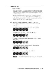
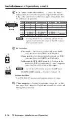
Page 25: ...external DIP switch TP R 15HD A be repositioned See Video jumpers or Video DIP switch in this chapter c RGB Output BNCs TP R BNC A and TP R BNC AV Connect the desired video output device to the rear panel output BNCs For RGBHV video use the R G B H HV and V BNCs R G B H HV V For RGBS video use the R G B and H HV BNCs R G B H HV V For RGsB or component video use the R R Y G Y and B B Y BNCs R G B H...

Page 26: ...nd B lines and their associated returns e DIP switches SOG switch Set this rear panel switch up for RGsB video and down for RGBHV or RGBS video C Sync switch Set this rear panel switch up for RGBS video and down for RGBHV or RGsB video C video switch TP R 15HD A only Configures the receiver for RGB or component S video composite video See Video DIP switch in this chapter N Set all three DIP switch...

Page 27: ... to properly wire an output connector Tip NO Ground Here Sleeve s Tip NO Ground Here Tip Ring Sleeve s Tip Ring Unbalanced Output Balanced Output L R AUDIO L R AUDIO CAUTION For unbalanced audio connect the sleeve s to the ground contact DO NOT connect the sleeve s to the negative contacts Figure 2 8 Audio output connector wiring N If only an audio signal no video is received connect a ground wire...

Page 28: ...ded with the unit Termination of TP cable Figure 2 10 details the termination of TP cables in accordance with the TIA EIA T 568A wiring standards Clip Down Side 1 1 2 3 6 4 5 7 8 2345678 12345678 Pin Wire color RGB video and audio AV Video and audio Signal Level Signal Level 1 White green Red V sync 0 35 V Video 0 35 V 2 Green Red V sync 0 35 V Video 0 35 V 3 White orange Audio power 15 V with 0 5...

Page 29: ...gth and tests the wire map attenuation NEXT PSNEXT ELFEXT PSELFEXT return loss ACR and PSACR All of these tests are critical for digital data transfer While all are important indicators of the quality of the cable termination the most critical testing parameters for video transfer are wire map T 568 A termination and pair length measurements The largest concern is equalization of skew between cabl...

Page 30: ...ion line measured as a percentage of the speed of light of TP cable is very close to that of conventional coaxial cable The similarity in NVP means that an additional length of coax equal to the length of pair skew placed on the receiver output equalizes the effects of pair skew figure 2 11 If UTP cable test measurement cannot be done pair skew can still be equalized by viewing a test pattern with...

Page 31: ...wer LED Amber indicates that power is applied but the transmitter is not connected to a receiver N On the TP R BNC AV if the composite video TP link is used and the RGB link is not used this LED will only light amber N This LED will only light amber if the transmitter is a VTT001 Green indicates that a transmitter is connected and any of the following grounding conditions exist The transmitter is ...

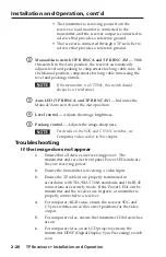
Page 32: ... Auto position d Level control Adjusts the image brightness e Peaking control Adjusts the image sharpness N For details on the SOG and C SYNC switches see Computer video earlier in this chapter Troubleshooting If the image does not appear 1 Ensure that all devices are receiving power The transmitter and receiver front panel Power LEDs indicate they are receiving power 2 Ensure the transmitter is r...

Page 33: ...ceive local power so are always grounded 11 Call the Extron S3 Sales Technical Support Hotline if necessary If the image is not displayed correctly 1 For computer RGB video if the output image looks too green ensure the receiver SOG switch is off 2 For computer video if the picture hangs off the edge of the screen adjust the transmitter H Shift control N DDSP disables the horizontal shift control ...

Page 34: ...Installation and Operation cont d 2 22 If the receiver Manual Auto LED flashes 1 The transmission distance may be too far for remote power Connect a local 15 V power supply to the transmitter 2 Check the RJ 45 connector for a loose connection ...

Page 35: ...TP Receivers A Appendix Specifications Accessories and Part Numbers Specifications Included Parts Accessories Cables Adapters ...

Page 36: ... source TP R BNC AV 1 analog RGBHV RGBS RGsB component video or S video or 1 S video and 1 NTSC PAL SECAM composite video from a single source or 3 NTSC PAL SECAM composite video from a single source and 1 NTSC PAL SECAM composite video TP R 15HD A 1 analog RGBHV RGBS RGsB component video or S video or 1 S video and 1 NTSC PAL SECAM composite video from a single source or 3 NTSC PAL composite vide...

Page 37: ...reo audio balanced unbalanced and 1 stereo audio unbalanced TP R 15HD A 1 stereo audio balanced unbalanced TP R BNC AV 2 stereo audio balanced unbalanced and 2 stereo audio unbalanced Connectors TP R 15HD A 1 3 5 mm 5 pole captive screw connector per input All other models 2 female RCA left right per input 1 3 5 mm 5 pole captive screw connector per input Impedance 50 ohms unbalanced 100 ohms bala...

Page 38: ... MBB 100 TP R BNC A TP R BNC AV Yes with optional 1U 9 5 deep rack shelf part 60 190 01 RSU 129 or 60 604 01 RSB 129 Furniture Mount TP R 15HD A Yes with optional mounting brackets part 70 077 01 MBU 125 or 70 077 02 MBD 129 TP R BNC A TP R BNC AV Yes with optional mounting brackets 70 077 01 MBU 125 or 70 077 02 MBD 129 Pole Mount TP R BNC A TP R BNC AV Yes with optional mounting kit part 70 077 ...

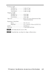
Page 39: ...ping weight TP R BNC A 4 lbs 2 kg TP R BNC AV 5 lbs 3 kg TP R 15HD A 2 lbs 1 kg Vibration ISTA 1A in carton International Safe Transit Association Regulatory Compliance Safety CE CUL UL EMI EMC CE C tick FCC Class A ICES VCCI MTBF 30 000 hours Warranty 3 years parts and labor N All nominal levels are at 10 N Specifications are subject to change without notice ...

Page 40: ...smitters or with older unmodified transmitters See Audio jumpers in chapter 2 Installation and Operation The TP T A 45 incorporates the redesigned audio circuits but cannot be jumpered for backwards compatibility Most redesigned modified receivers and transmitters have an identifying label The TP T A 45 incorporates the redesigned audio circuits but does not have an identifying label Extron Access...

Page 41: ...569 03 25 Enhanced Skew Free A V UTP 26 569 04 Skew Free A V cable Part number 35 Enhanced Skew Free A V UTP 26 569 05 50 Enhanced Skew Free A V UTP 26 569 06 75 Enhanced Skew Free A V UTP 26 569 07 100 Enhanced Skew Free A V UTP 26 569 08 25 Enhanced Skew Free A V UTP Plenum 26 570 04 35 Enhanced Skew Free A V UTP Plenum 26 570 05 50 Enhanced Skew Free A V UTP Plenum 26 570 06 75 Enhanced Skew Fr...

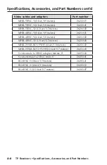
Page 42: ...eet 3 7 meters 26 260 02 MHR 4 BNC 3 3 feet 0 9 meters 26 210 01 MHR 4 BNC 6 6 feet 1 8 meters 26 210 02 MHR 4 BNC 12 12 feet 3 7 meters 26 210 03 MHR 2 SVM M 6 SVHS 6 feet 1 8 meters 26 316 02 MHR 2 SVM M 12 SVHS 12 feet 3 7 meters 26 316 03 S video male to 2 BNC adapter female 8 26 353 02 S video female to 2 BNC male 8 26 353 01 RG6 BNC 3 3 feet 0 9 meters 26 383 01 RG6 BNC 6 6 feet 1 8 meters 2...

Page 43: ... Emirates Dubai This Limited Warranty does not apply if the fault has been caused by misuse improper handling care electrical or mechanical abuse abnormal operating conditions or non Extron authorized modification to the product If it has been determined that the product is defective please call Extron and ask for an Applications Engineer at 714 491 1500 USA 31 33 453 4040 Europe 65 383 4400 Asia ...

Page 44: ...7 FAX Extron Europe 800 3987 6673 Inside Europe Only 31 33 453 4040 31 33 453 4050 FAX Extron Asia 800 7339 8766 Inside Asia Only 65 6383 4400 65 6383 4664 FAX Extron Japan 81 3 3511 7655 81 3 3511 7656 FAX Extron China 400 883 1568 Inside China Only 86 21 3760 1568 86 21 3760 1566 FAX Extron Middle East 971 4 2991800 971 4 2991880 FAX 2009 Extron Electronics All rights reserved ...

Reviews: