Mounting
The base allows these touchpanels to be placed on any suitable flat surface.
For additional security, the touchpanels can be attached to a table or desktop.
1.
Connect an Ethernet cable to the LAN/PoE input (see
figure 3
,
F
, on the next page) and run the cable through the cable
guide (
D
).
2.
Drill two holes through the desktop from underneath, 3.07" (78 mm) apart.
3.
Attach the touchpanel with two #8-32 screws through the desktop from underneath into the two mounting holes in the base
of the unit (
A
).
The touchpanels can also be mounted with the optional Extron SMA-2 swivel mount adapter, which allows them to be secured
to the table and swivel up to 180° in either direction. Attach the SMA-2 to the mounting holes in the base (
A
) and follow the
instructions in the
SMA-2 Swivel Mount Adapter Kit User Guide
.
Front Panel Features
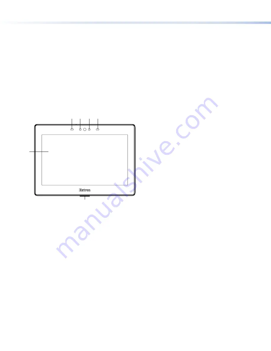
Figure 1 shows the TLP Pro 725T Series front panel. The front panels of the TLP Pro 525T and TLP Pro 1025T Series are very
similar.
B
B C
C
E
E
D
D
A
A
B
B
Figure 1.
TLP Pro 725T Front Panel
A
LCD touchscreen
z
TLP Pro 525T Series
— 5-inch, 800x480 resolution touchscreen
z
TLP Pro 725T Series
— 7-inch, 1024x600 resolution touchscreen
z
TLP Pro 1025T Series
— 10-inch, 1280x800 resolution touchscreen
The touchscreen is made with Corning Gorilla Glass, which is stronger and more scratch-resistant than standard glass, while
maintaining touch sensitivity, color saturation, and brightness.
B
Motion sensor
(2) — Detects motion between three to five feet from the touchpanel, and at least 15° from the center axis.
z
When no motion has been detected for a user-defined period of time, the touchpanel enters sleep mode.
z
When motion is detected by the sensor, the screen display is restored and active.
C
Communication LED
— Shows the configuration and connection status of the touchpanel:
z
Unlit during normal operation (the touchpanel is configured and connected to an IP Link Pro control processor).
z
Blinks red if the touchpanel has been configured but is not connected to an IP Link Pro control processor.
z
Solidly lit if the touchpanel has not been configured.
The indicator can be toggled between enabled and disabled, using the
Setup Menu
(see page 4).
D
Light sensor
— Monitors ambient light level and adjusts screen brightness, based on the settings configured using the
Setup Menu
.
E
Status light
— Can be programmed to provide system feedback:
z
Light red or green
z
Blink or light continuously
For information about configuring or programming this light, see the
Global Configurator Help File
or the
Global Scripter Help
File
.
2
TLP Pro 525T, 725T, and 1025T Series • Setup Guide (Continued)


