Extron electronics SW2 MTP T 15HD A User Manual Download Page 14

SW MTP T Series Switchers • Operation

SW MTP T Series Switchers • Operation

Operation, cont’d

Front Panel Controls and Indicators

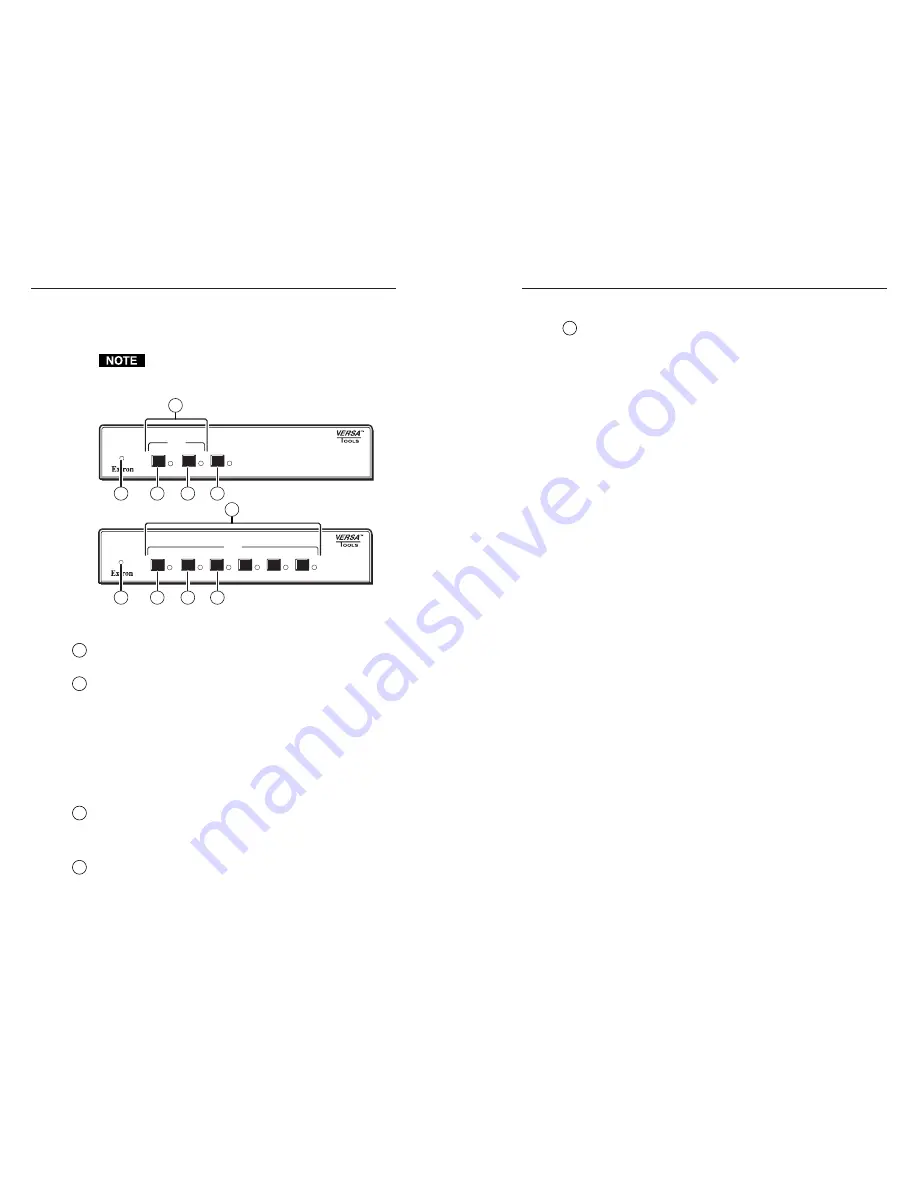
Figure 3-1 shows the controls and indicators on the front panel
of the SW2 MTP T 15HD A and SW6 MTP T 15HD A switchers.

The SW4 MTP T 15HD A switcher has fewer input
buttons than the SW6 MTP T 15HD A, but is otherwise
identical.

AUTO

SWITCH

4

SW6 MTP T 15HD A

1

MODE

2

NORMAL

3

AUTO

6

5

INPUT

AUTO

SWITCH

SW2  MTP T 15HD A

1

MODE

2

NORMAL

AUTO

INPUT

1

3

4

5

2

1

3

4

5

2

Figure 3-1 — SW MTP T switcher front panels

1

Auto Switch LED

 — When this LED is on, it indicates that the

auto switch mode is active.

2

Input selection buttons and LEDs

 — When the auto switch

mode is off, use these buttons to select an input.  The LED for
the selected input lights.  When audio is broken away (available
under RS-232 control only, see chapter 4, Remote Control), the
selected video input’s LED is lit steadily and the selected
audio’s LED blinks.

The LEDs continue to indicate the selected input when auto
switch mode is on.  If no input LED is lit, no input has active
sync pulses and no input is selected.

3

Mode button

 — Use this button, with either the Auto or

Normal button, to manually turn auto switch mode on or off.

Mode is a secondary function of the Input 1 button.

4

Normal button

 — Use this button, with the Mode button, to

manually turn auto switch mode off.

Normal is a secondary function of the Input 2 button.

5

Auto button

 — Use this button, with the Mode button, to

manually turn auto switch mode on.

On 4-input and 6-input switchers, Auto is a secondary function
of the Input 3 button.

Front Panel Operations

Plug in all system components and turn on the input devices
(such as desktop computers and laptops) and the output
monitors.  Select an input.  The image should appear on the
monitor connected to the selected output.

Normal and auto switch mode

All SW MTP T switchers can operate in either normal (manual)
mode or auto switch mode.  In auto switch mode, the highest
numbered input with a sync signal present is automatically
selected for output.  If no sync signal is present, no input is
selected.  Front panel input selection is blocked while in auto
switch mode.  However, the front panel LEDs remain functional
and the buttons can be used to change the mode.

Selecting normal switch mode

Press and hold the Input 1/Mode button while you press and
release the Input 2/Normal button.  The Auto Switch LED turns
off, indicating normal switch mode.  Release the Input 1/Mode
button.

Selecting auto switch mode

Press and hold the Input 1/Mode button while you press and
release the Input 3/Auto button.  The Auto Switch LED turns
on, indicating auto switch mode.  Release the Input 1/Mode
button.

Selecting an input in normal switch mode

To select an input using the front panel buttons, press and
release the button for the desired input (must be in normal
switch mode).  The LED for the selected input lights.

An input can also be selected by an RS-232 device or a remote
control device (see chapter 4, Remote Control).

3-2

3-3

Summary of Contents for SW2 MTP T 15HD A

Page 1: ...33 453 4050 Extron Electronics Asia 135 Joo Seng Road 04 01 PM Industrial Building Singapore 368363 65 6383 4400 Fax 65 6383 4664 Extron Electronics Japan Daisan DMJ Building 6F 3 9 1 Kudan Minami Ch...

Page 2: ...Wartung Alle Wartungsma nahmen sollten nur von qualifiziertem Servicepersonal durchgef hrt werden Die internen Komponenten des Ger tes sind wartungsfrei Zur Vermeidung eines elektrischen Schocks vers...

Page 3: ...output cable Step 5 Connect the other end of the TP cable to an MTP R 15HD A or MTP RL 15HD A receiver Quick Start Guide SW MTP T Series QS 1 1 Video Input Connector Audio Input Connector 5 Pin 1 Red...

Page 4: ...ojectors monitors speakers SW MTP T Series switcher contact closure RS 232 controller and input devices computers audio sources Input selection normal switch mode Select an input using the front panel...

Page 5: ...3 Timeout 4 4 Using the command response table 4 4 Symbol definitions 4 4 Command response table for SIS commands 4 5 Windows Based Program Control 4 8 Installing the software 4 8 Using the software 4...

Page 6: ...tion 1 2 The MTP switcher requires either an MTP R 15HD A MTP RL 15HD A or VTR001 receiver The receiver inputs the transmitted proprietary signal and converts the signal back into its high resolution...

Page 7: ...50 121 9 m 1600 x 1200 250 76 2 m 300 91 4 m 300 91 4 m 450 137 1 m Video format Pre Peak off Pre Peak on Max range high quality Max range variable quality The recommended distance when using VTR001 r...

Page 8: ...e bottom side of the unit and place the unit in the desired location Rack mounting For optional rack mounting do not install the rubber feet Mount the switcher on a standard or basic 19 1U VersaTools...

Page 9: ...from one side of the unit Retain the screws for possible later reassembly without the bracket 3 Attach one bracket to the side of the unit using the longer screws included in the kit 4 Repeat steps 2...

Page 10: ...h the screws through the bracket slots 7 Slide the switcher slightly forward or back then tighten all four screws to secure the unit in place Rear Panel Features and Connections All connectors are on...

Page 11: ...n C chroma G and G return Y luma pins For composite video use the G pin and the associated return pin 3 Audio input connectors Plug a 3 5 mm stereo audio plug into this jack for unbalanced audio input...

Page 12: ...kit may need to be modified by removing pins or cutting wires If unneeded pins are connected the switcher may hang up See chapter 4 Remote Control for additional information TP Cable Termination RJ 45...

Page 13: ...ries Switchers Installation Installation cont d SW MTP T Series Switchers 3 Chapter Three Operation Front Panel Controls and Indicators Front Panel Operations Rear Panel Pre Peak Switch Skew Delay Pro...

Page 14: ...2 button 5 Auto button Use this button with the Mode button to manually turn auto switch mode on On 4 input and 6 input switchers Auto is a secondary function of the Input 3 button Front Panel Operat...

Page 15: ...ew Delay Problems CAT 5 TP cable can lead to registration errors between the red green and blue video signals Pair skew can be measured with test equipment or identified by viewing a crosshatch test p...

Page 16: ...quence When a command is valid the switcher executes the command and sends a response to the host device All responses from the switcher to the host end with a carriage return and a line feed CR LF wh...

Page 17: ...itch mode 4 5 4 4 Command response table for SIS commands Command ASCII Command Response Additional description host to switcher switcher to host Input selection The two select video commands X1 and X...

Page 18: ...Audio mute status Front panel mode Set normal switch mode 1 F1 Set switch mode to normal Set auto switch mode 2 F2 Set switch mode to auto auto switch Front panel lockout executive mode Lock front pan...

Page 19: ...resent Windows Based Program Control The Universal Switcher Control Program part 29 031 01 is compatible with Windows 3 1 3 11 Windows 95 98 Windows NT Windows ME Windows XP and Windows 2000 and provi...

Page 20: ...ate to the folder where you saved the firmware upgrade file Select the file Ensure that the firmware upgrade is for the SW MTP Series switcher Valid firmware files must have the file extension bin Any...

Page 21: ...the table on page 4 2 To select a different input number using a contact closure device momentarily short the pin for the desired input number to logic ground pin 5 To force one of the inputs to be al...

Page 22: ...tocol 9600 baud 8 data bits 1 stop bit no parity Serial control pin configurations 2 TX 3 RX 5 GND Contact closure RS 232 9 pin female D connector shared with serial control Contact closure pin config...

Page 23: ...for Windows Extron s Simple Instruction Set SIS General Power Supplied by an external power supply The SW MTP Series transmitters cannot supply remote power to or receive remote power from attached re...

Page 24: ...mended for Ethernet LAN applications Enhanced Skew Free A V cable cut various lengths 26 569 xx Enhanced Skew Free A V 1000 Bulk non plenum 22 141 03 Enhanced Skew Free A V 1000 Bulk plenum 22 142 03...

Page 25: ...SW MTP T Series Switchers Reference Information Reference Information cont d A 8...

Reviews: