2
SMD 202 • Setup Guide (Continued)
Output Connections
E
HDMI output
– Connect an HDMI (or DVI with suitable adapter) display device to the HDMI output connector. The EDID of a
connected display is read and the output automatically configured. For non-standard displays or devices, see the
SMD 202
User Guide
for additional output resolutions and format settings.
G
Audio output
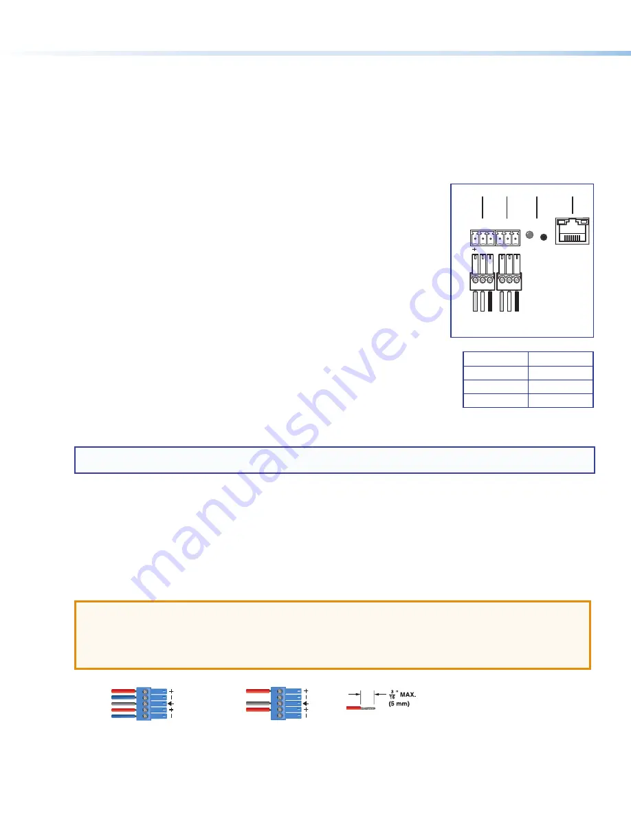
– Connect a balanced or unbalanced stereo (or dual mono) line level audio device to this 5-pole 3.5 mm
captive screw connector (see
figure 1
,
G
on page 1). Wire the connector as shown in figure 3, below.
ATTENTION
:
•
For unbalanced audio, connect the sleeves to the ground contact. DO NOT connect the sleeves to the negative (–)
contacts.
•
Pour l’audio asymétrique, connectez les manchons au contact au sol. Ne PAS connecter les manchons aux
contacts négatifs (–).
Balanced Audio Output
Unbalanced Audio Output
Do not tin the wires!
Left
Tip
Sleeve(s)
NO Ground Here
NO Ground Here
Tip
Right
Tip
Sleeve(s)
Ring
Ring
Tip
Left
Right
Figure 3.
Audio Output Captive Screw Connector Wiring
Control System and External Device Connections
The SMD 202 can be configured and controlled from the RS-232 port or the front panel mini-type B USB config port using
DataViewer, or from the LAN port using a standard Web browser. Since the LAN port must be connected for streaming source
input, Extron recommends also using it for configuration and remote control of the SMD 202.
B
USB host port
– Connect a USB compatible storage device to this port (see
figure 1
,
B
on page 1).
C
SD Card slot
– This slot supports SD, SD-HC, and SD-XC card types up to 512 Gigabyte card capacity and Class
10 (UHS-1) data rates up to 25 Mbytes/sec (see
figure 1
,
C
on page 1). Mounted media is listed in the user file system
under the media folder. The media folder and contents are accessible from the
File
browser of the default Web interface
(see
Connect to the SMD 202 and Play a File or Stream:
on page 6).
H
IR In
– Connect an (optional) IR receiver to this 3-pole 3.5 mm captive screw connector
to extend the range of the optional IR remote control (see figure at right). The handheld IR
remote provides access to the on-screen menus for configuration and for direct control
over playback (see the
SMD 202 User Guide
).
I
RS-232
— To control the SMD 202 using SIS commands over RS-232, connect the
host RS-232 cable to the rear panel (see the figure at right) with a 3-pole captive screw
connector for bi-directional (±5 V) serial host control. The default protocol for this port is
9600 baud
,
no parity
,
8 data bits
,
1 stop bit
, and
no flow control (handshaking)
.
J
Reset button and LED
— The SMD 202 has four reset modes to restore default
configuration settings or all settings back to factory defaults (see figure at right). The
LED indicates the desired reset mode, and provides the reset status during the reset
operation. For information on using the reset mode, see the
SMD 202 User Guide
.
K
RJ-45 Ethernet connector (LAN)
— Use a standard Ethernet cable to connect to a
network (see illustration at right). The table (right) includes the default network settings
of the SMD 202.
The left side (amber) LED indicator on the LAN connector blinks in a pattern to indicate
the network link speed.
•
Three blinks, pause
— 1 Gbps
•
Two blinks, pause
— 100 Mbps
•
One blink, pause
— 10 Mbps
NOTE:
The SMD 202 LAN connection uses Auto MDI-X allowing direct connection of a control PC using a standard
straight through Ethernet cable.
IP Address: 192.168.254.254
Subnet Mask: 255.255.0.0
Default Gateway: 0.0.0.0
DHCP: OFF
Tx Rx G
S G
RS-232
RESET
IR IN
LAN
H I
J
K
Ground
Receiv
e
Tr
ansmit
Connected RS-232
Device Pins
+
S
IR
Transmitter
G


