4
RCP 101 D Remote Control Panel • Setup Guide (Continued)
Step 3: Mount the Remote Control Plate
The RCP 101 D can be installed directly into the wall using
a 1-gang wall mounting bracket (mud ring) or a UL Listed
electrical junction box.
The RCP 101 D ships with one black and one white
wallplate. Either wallplate can be used to complement the
surroundings.
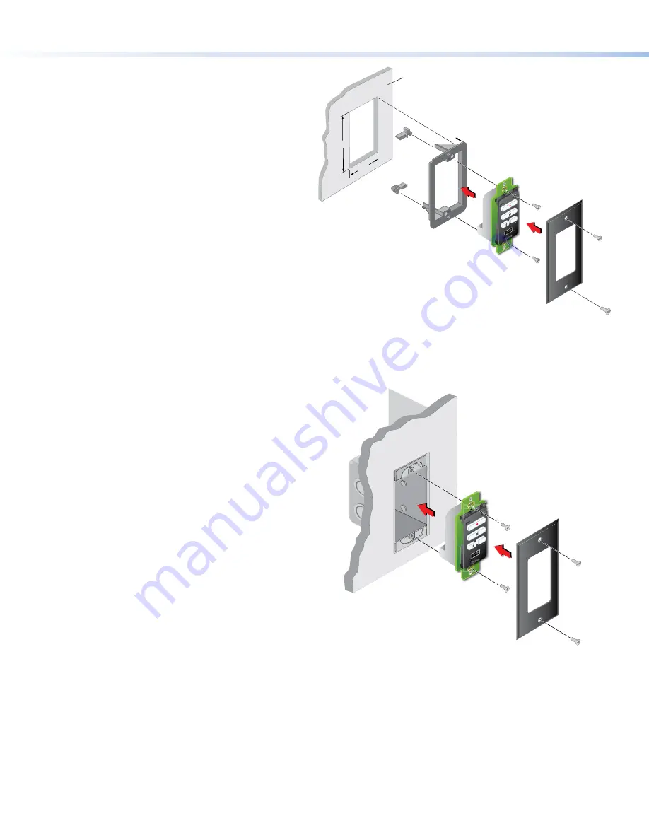
Mounting with a wall mounting bracket
Mount the RCP 101 D with a wall mounting bracket as
follows:
1.
Mark the position of the hole (3.61" [9.17 cm] H x 2.13"
[5.42 cm] W) on the wall in the desired location. Use a
level to ensure hole is marked at the correct angle.
2.
Use a drywall saw to cut a hole (
1
).
3.
Insert the mounting bracket into the hole. Use a
screwdriver to turn and tighten the locking arms until
they clamp the mud ring to the mounting surface (
2
).
Do not overtighten.
4.
Attach cables as described in
RCP 101 D Rear Panel
Features
on page 2.
5.
Use the two provided Phillips head screws to secure
the button panel to the mounting bracket (
3
).
6.
Use the two screws provided to secure the Decorator-
style wallplate to the button panel (
4
).
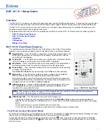
Mounting with a UL Listed electrical junction
box
The wall box is not provided and must be purchased
separately. Ensure the wall box is the correct size for the
RCP 101 D.
1.
Install the junction box by following the instructions
provided by the manufacturer.
2.
Locate a suitable wall stud and mark the hole on
the wall. Use a level to ensure hole is marked at the
correct angle.
3.
Use a drywall saw to cut the hole. Follow the
instructions of the wall box manufacturer for the
correct dimensions of the hole to be cut.
4.
Use at least two screws or nails to secure the wall box
to the wall stud.
5.
Attach cables as described in
RCP 101 D Rear Panel
Features
on page 2.
6.
Use the two provided Phillips head screws to secure
the button panel to the mounting bracket (
1
).
7.
Use the two screws provided to secure the Decorator-
style wallplate to the button panel (
2
).
Wall
2.13"
3.61"
Wall Mounting
Bracket
Locking Arm
Wallplate
RCP 101 D
3
3
4
4
Ext
ron
Ext
ron
MARK
RECORD
USB
STORAG
E
MARK
1
1
2
2
Figure 4.
Mounting with a Wall Mounting Bracket
Electrical
Junction
Box
1
1
Wallplate
2
2
1
1
1
1
1
1
1
1
Ext
ron
Ex
tron
MARK
RECORD
USB STO
RAG
E
MARK
RCP 101 D
Figure 5.
Mounting with an Electrical Junction Box
Removing the RCP 101 D
If you need to remove the RCP 101 D from the wall, you can do so by reversing the steps shown in figure 4 or figure 5:
1.
Disconnect the RCP 101 from the power source.
2.
Undo the two screws securing the faceplate to the control plate and remove the wallplate (figure 5,
2
).
3.
Undo the two screws securing the control plate to the wall mounting bracket or the electrical junction box (
1
).
4.
Remove the power cable (
figure 2
,
B
) and the USB cable (
C
). If necessary, cut the zip tie securing the USB cable to the
cable anchor (
C
).


