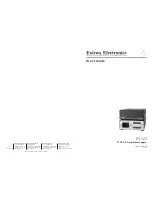


PS 123 12 VDC, 3 Amp Power Supply • User's Guide
PS 23, cont’d
PS 123 12 VDC, 3 Amp Power Supply • User's Guide
C
Stripping the wires to expose less than the
recommended amount may cause them to slide out
of the connector too easily, even if they are tightly
pinched by the captive screws.
C
Do not tin the stripped power supply leads before
attaching the captive screw plug to them. Tinned
wires are not as secure in the captive screw
connectors and can be easily pulled out. They may
also break after being bent several times.
3
.
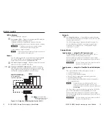
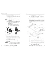
Slide the leads into the supplied 2-pin captive screw plug
and secure them, using an Extron Tweeker or other small
screwdriver.
4
.
Use the supplied tie wrap to strap the power cord to the
extended tail of the connector.
Mounting options
There are several optional accessories for mounting the PS 123.
They include the following Extron part numbers:
• RSU 129 1U 9.5" Universal Rack Shelf (part #
60-190-01
)
• RSB 129 1U 9.5” Deep Basic Rack Shelf (part #
60-604-01
)
• MBU 125 1U Under-Desk Mounting (part #
70-077-01
)
• PMK 350 Low Profile Multi-product (part #
70-563-02, -03
)
Projector Mounting Kit
• PMK 450 Easy Installation
(part #
70-618-02, -03
)
Multi-product Projector Mounting Kit
Rack mounting
UL rack mounting requirements
The following Underwriters Laboratories (UL) requirements
pertain to the installation of the PS 123 into a rack.
•
Elevated operating ambient temperature
— If the
equipment is installed in a closed or multiunit rack
assembly, the operating ambient temperature of the
rack environment may be greater than room ambient
temperature.
Therefore, consider installing the equipment in an
environment compatible with the maximum ambient
temperature (Tma) specified by the manufacturer. For the
PS 123, the Tma is 122 °F (50 °C).
•
Reduced air flow
— Installation of the equipment in a rack
should be such that the amount of air flow required for
safe operation of the equipment is not compromised.
•
Mechanical loading
— Mounting of the equipment in
the rack should be such that a hazardous condition is not
created due to uneven mechanical loading.
•
Circuit overloading
— Consideration should be given to
the connection of the equipment to the supply circuit and
the effect that overloading of the circuits might have on
overcurrent protection and supply wiring. Appropriate
consideration of equipment nameplate ratings should be
used when addressing this concern.
•
Reliable earthing (grounding)
— Reliable earthing
of rack-mounted equipment should be maintained.
Particular attention should be given to supply connections
other than direct connections to the branch circuit (e.g. use
of power strips.
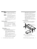
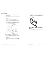
Rack mounting procedure
For optional rack mounting, mount up to four PS 123s on
an RSU 129 9.5" 1U Universal Rack Shelf (part #
60-190-01
)
(figure 8) or an RSB 129 9.5" 1U Basic Rack Shelf (part
#
60-604-01
).
Use 2 mounting holes on
opposite corners.
(2) 4-40 x 3/16"
Screws
1U Universal Rack Shelf
Both front false faceplates
use 2 screws.
QuarterRackStandardShelf
1/4 Rack Width Front False
Faceplate
1/2 Rack Width Front False
Faceplate
Figure 8 — Rack mounting the PS 123
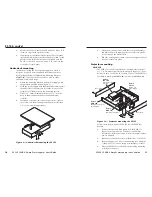
1
. If feet were previously installed on the bottom of the
PS 123 unit, remove them.