Virtualization/Control Software, cont’d
Matrix 12800 Switchers • Virtualization/Control Software
3-30
PRELIMINAR
Y
Ties as Crosspoints
—
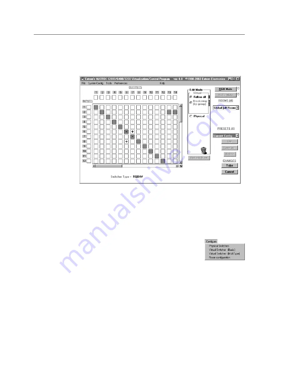
Displays ties as a matrix of inputs and outputs (figure 3-20).
Made ties are indicated as blue (video and audio) boxes or boxes of the
applicable color for each video plane. Ties that will take effect when you click
on the
Take
button are indicated by +. Ties that will be broken when you
click on the
Take
button are indicated by –.
Figure 3-20 — Ties shown as crosspoints
Virtual map screen menu bar options
The following drop-down menus and menu selections are available from the virtual
map screen menu bar:
Return to main
Exits the Virtual Map screen and returns to the main screen.
Configure
menu
Physical Switchers
—
Displays the Physical Configuration
screen, from which you can view and change the type
and size of all BMEs in the system.
Virtual Switcher - (Basic)
—
Displays the Virtual
Configuration screen, from which you can view and change the virtual plane
assignment, the virtual size, how the virtual planes are ordered, and the sync
format for each BME.
Virtual Switcher - (MultiType)
—
Displays the Virtual Configuration Wizard
screen, which provides a simpler means of virtualizing the system when
multiple video types are present in the system.
Room Configuration —
Displays the Room Mapper screen, from which you can
assign outputs to specific rooms for the purposes of creating room presets.


