


4
IPL Pro Series • Setup Guide (Continued)
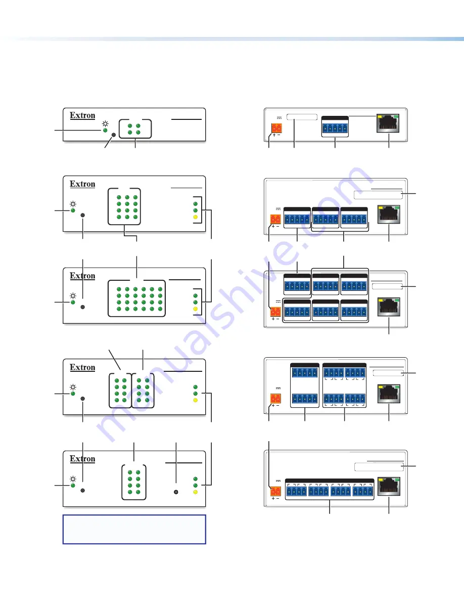
Front Panel Features
R
1000
LINK
ACT
COM
3
1
2
6
4
5
RTS
CTS
Tx
Rx
R
1000
LINK
ACT
IPL PRO S3
3
1
2
RTS
CTS
Tx
Rx
COM
COM
RTS
CTS
Tx
Rx
R
IPL PRO S1
IPL PRO S6
R
1000
LINK
ACT
3
4
1
2
3
4
1
2
7
8
5
6
7
8
5
6
RELAYS
INPUT
R
1000
LINK
ACT
IR
IR/SERIAL
6
5
7
8
2
1
3
4
IPL PRO CR88
IPL PRO IRS8
NOTE:
Numbers adjacent to LEDs
correspond to the like-numbered
rear panel ports.
COM (Serial)
LEDs
COM (Serial)
LEDs
Reset
Button
(recessed)
Reset
Button
(recessed)
Power
LED
Power
LED
Power
LED
LAN/
Network
LEDs
Reset
Button
(recessed)
Power
LED
Power
LED
LAN/
Network
LEDs
IR/Serial
LEDs
Contact Input
LEDs
Relay
LEDs
IR Learning
Receiver
Figure 2.
IPL Pro Series Front Panel Features
Rear Panel Features
POWER
12V
0.2A MAX
POWER
12V
0.3A MAX
POWER
12V
0.3A MAX
IPL PRO S3
LAN / PoE
G
Tx Rx
RTS CTS
COM
G
Tx Rx
RTS CTS
COM 1
G
Tx Rx
RTS CTS
COM 3
G
Tx Rx
RTS CTS
COM 2
G
Tx Rx
RTS CTS
COM 1
G
Tx Rx
RTS CTS
COM 3
G
Tx Rx
RTS CTS
COM 2
G
Tx Rx
RTS CTS
COM 4
G
Tx Rx
RTS CTS
COM 6
G
Tx Rx
RTS CTS
COM 5
LAN / PoE
IPL PRO S6
IPL PRO S1
LAN / PoE
POWER
12V
0.3A MAX
POWER
12V
0.3A MAX
3
4
2
1
1
G
7
8
6
5
G
G
S
G
S
INPUT
2
1
2
G
S
G
S
7
8
G
S
G
S
7
8
G
S
G
S
7
8
3
4
5
6
7
8
RELAYS
LAN / PoE
LAN / PoE
IR/SERIAL
IPL PRO CR88
IPL PRO IRS8
MAC: 00-05-A6-
XX-XX-XX
S/N: ####### E######
MAC: 00-05-A6-
XX-XX-XX
S/N: ####### E######
MAC: 00-05-A6-
XX-XX-XX
S/N: ####### E######
MAC: 00-05-A6-
XX-XX-XX
S/N: ####### E######
00-05-A6-XX-XX-XX
MAC: 00-05-A6-
XX-XX-XX
S/N: ####### E######
MAC: 00-05-A6-
XX-XX-XX
S/N: ####### E######
MAC: 00-05-A6-
XX-XX-XX
S/N: ####### E######
00-05-A6-XX-XX-XX
5-pole COM
RS-232 ports
5-pole COM
RS-232/RS-422/
RS-485 ports
MAC
address
Power
input
connector
Power
input
connector
MAC
address
MAC
address
LAN/PoE
(Ethernet)
connector and LEDs
5-pole COM
RS-232 port
LAN/PoE
(Ethernet)
connector and LEDs
LAN/PoE
(Ethernet)
connector and LEDs
Contact
input
ports
Relay
ports
MAC
address
Power
input
connector
MAC
address
LAN/PoE
(Ethernet)
connector and LEDs
LAN/PoE
(Ethernet)
connector and LEDs
IR/Serial output
ports
Figure 3.
IPL Pro Series Rear Panel Features
Panels and Locations of Features
Location and quantity of LEDs and corresponding connectors vary by model, but the functions and port wiring are identical
across models for each port type.


