background image

3

Network Communication Setup

Network setup is essential prior to configuration. Use the following flowchart as a guide to setting up the control processor for 
network use.

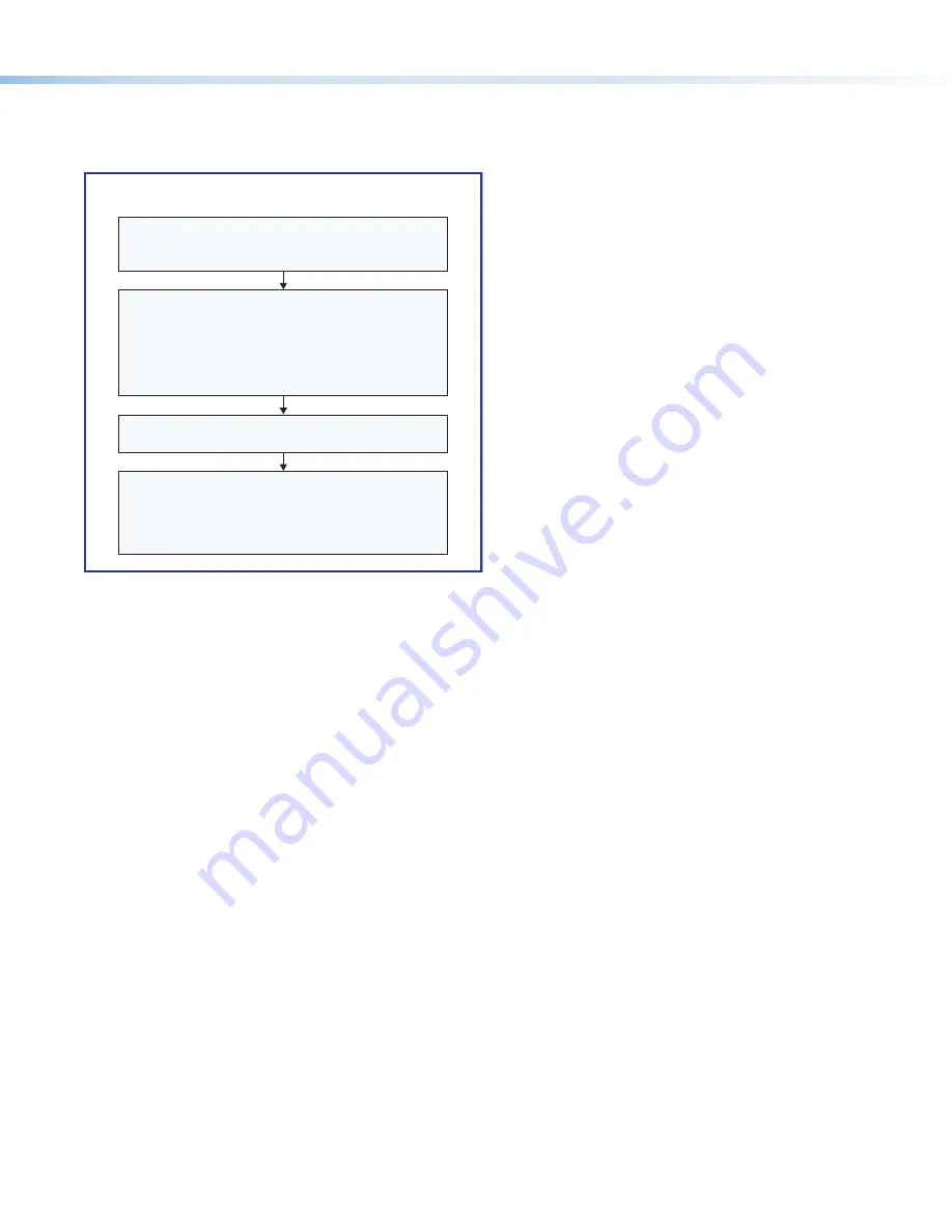
Open the Toolbelt software from within 

Global Configurator (GC Professional or GC Plus mode) 

or as the stand-alone application. 

Start Device Discovery.

Toolbelt displays a list of all Extron control devices 

connected to the network.

Using the MAC address, locate the desired device 

in the list and select it.

Network Communication Setup

Connect the control processor 

and PC to the same network. 

Apply power to all devices.

Use the Set IP feature in Toolbelt 

or


use the Toolbelt 

Manage

 > 

Network Settings

 tab 

feature to enter the IP address, subnet address, 

and gateway, then configure other network settings 

as needed.

Figure 1. 

Network Setup

Mounting

Securely mount the control processor and other devices and attach cables using the wiring section (

Cabling and Features

 on 

page 5) as a wiring guide. Optional 1U rack shelves and furniture mounting bracket kits are available for use with the control 
processor. Read and follow the instructions and UL guidelines that come with the rack shelf or mounting kit for installation 
procedures.
See the product-specific page at 

www.extron.com

 for a list of compatible accessories for mounting your control processor.

Summary of Contents for IPL Pro Series

Page 1: ... yourself with the features of the control processor see Front Panel Features on page 4 and Rear Panel Features and of any TouchLink Pro touchpanels that will be part of the system Download and install the latest version of the following Toolbelt software for discovering the control processor and other control products on the network for managing core settings and for upgrading firmware when neede...

Page 2: ...the system start and use GUI Designer to design save and build the graphical user interface GUI layout for the touchpanels Using GC create a new GC Plus or GC Professional project and configure the control processor and other IP Link Pro devices The configuration tells the control processor how its ports function what to monitor how to control other products when to do things which touchpanels to ...

Page 3: ...ork Apply power to all devices Use the Set IP feature in Toolbelt or use the Toolbelt Manage Network Settings tab feature to enter the IP address subnet address and gateway then configure other network settings as needed Figure 1 Network Setup Mounting Securely mount the control processor and other devices and attach cables using the wiring section Cabling and Features on page 5 as a wiring guide ...

Page 4: ... Tx Rx RTS CTS COM 6 G Tx Rx RTS CTS COM 5 LAN PoE IPL PRO S6 IPL PRO S1 LAN PoE POWER 12V 0 3A MAX POWER 12V 0 3A MAX 3 4 2 1 1 G 7 8 6 5 G G S G S INPUT 2 1 2 G S G S 7 8 G S G S 7 8 G S G S 7 8 3 4 5 6 7 8 RELAYS LAN PoE LAN PoE IR SERIAL IPL PRO CR88 IPL PRO IRS8 MAC 00 05 A6 XX XX XX S N E MAC 00 05 A6 XX XX XX S N E MAC 00 05 A6 XX XX XX S N E MAC 00 05 A6 XX XX XX S N E 00 05 A6 XX XX XX MA...

Page 5: ...xternal Power Supply 12 VDC 0 5 A max Extron P N 28 331 57LF NOTE IPL Pro Series control processors accept power over Ethernet PoE through the LAN port in addition to network communication see Control LAN Ethernet on page 6 for cabling and details Both an external power supply and PoE can be connected to the control processor simultaneously The IPL uses PoE when it is available but can switch seam...

Page 6: ... Control LAN Ethernet 1000 LINK ACT LAN PoE I IPL PR PRO S6 5 A6 XX XX XX E 5 A6 XX XX XX Rear Panel Front Panel RJ 45 Connector Insert Twisted Pair Wires Pins 1 2 3 4 5 6 7 8 1000 Mbps Connection Network is active Data is being sent received Link LED Activity LED LAN PoE Ethernet Default protocol IPL IP address 192 168 254 250 Gateway IP address 0 0 0 0 Subnet mask 255 255 255 0 DNS address 127 0...

Page 7: ...input Each port senses external switch or contact closure by using a 1k ohm pull up resistor in a TTL 5 VDC circuit Use these ports to monitor or trigger events and functions toggle relays issue commands send e mail once configured Input LEDs Light when the corresponding ports are active tied to ground logic low Rear Panel Front Panel Switches sensors relays or similar items Share the same ground ...

Page 8: ...rmware version 3 0 or higher By default DHCP is off and the unit uses a static IP address When you disable the DHCP client the unit reverts to using the previously set static IP address Reset All IP Settings Press and hold the front panel Reset button for 6 seconds After the Power LED blinks twice release and momentarily press the Reset button Use this mode to reset all network settings to factory...

Page 9: ... a link for contacting an Extron support representative who can provide you access to the latest version To obtain Extron control product software you must have an Extron Insider account Extron provides training to our customers on how to use the software Access to the full features of Global Configurator Professional is available to users who successfully complete Extron Control Professional Cert...

Page 10: ...schedules timers macros and local variables Add touchpanels or other interfaces if used to the project Configure ports on the control processor Import GUI layouts and configure the touchpanels or other interfaces Test the system make adjustments finalize configuration Save the project Build and upload the configuration to the control processor If desired or required install a new security certific...

Reviews: