background image

A-9

DVS 406 • Appendix

Serial Digital Interface (SDI) Card Installation

The optional SDI card may be installed in the scaler if it does not already have an
input for a serial digital interface signal.  We recommend that you send the unit
in to Extron for service and updates.

Changes to electronic components must be performed by authorized
service personnel only.

Follow these steps to install an SDI card in the DVS 406.

1.

Disconnect the AC power cord from the DVS 406 to remove power from the
unit.  Then disconnect the input/outut cables.

To prevent electric shock, always unplug the DVS 406 scaler from the
AC power source before opening the enclosure.

2.

Remove the scaler from the rack or furniture.

3.

Remove the cover of the scaler (the top half of the enclosure) by removing
the screws, then lifting the cover straight up.  See the top cover removal
diagram in the “Firmware Upgrade Installation” section.

Do not touch any switches or other electronic components inside the
scaler.  Doing so could damage the scaler.  Electrostatic discharge (ESD)
can damage IC chips even though you cannot feel it.  You must be
electrically grounded before proceeding with any electronic component
replacement.  A grounding wrist strap is recommended.

4.

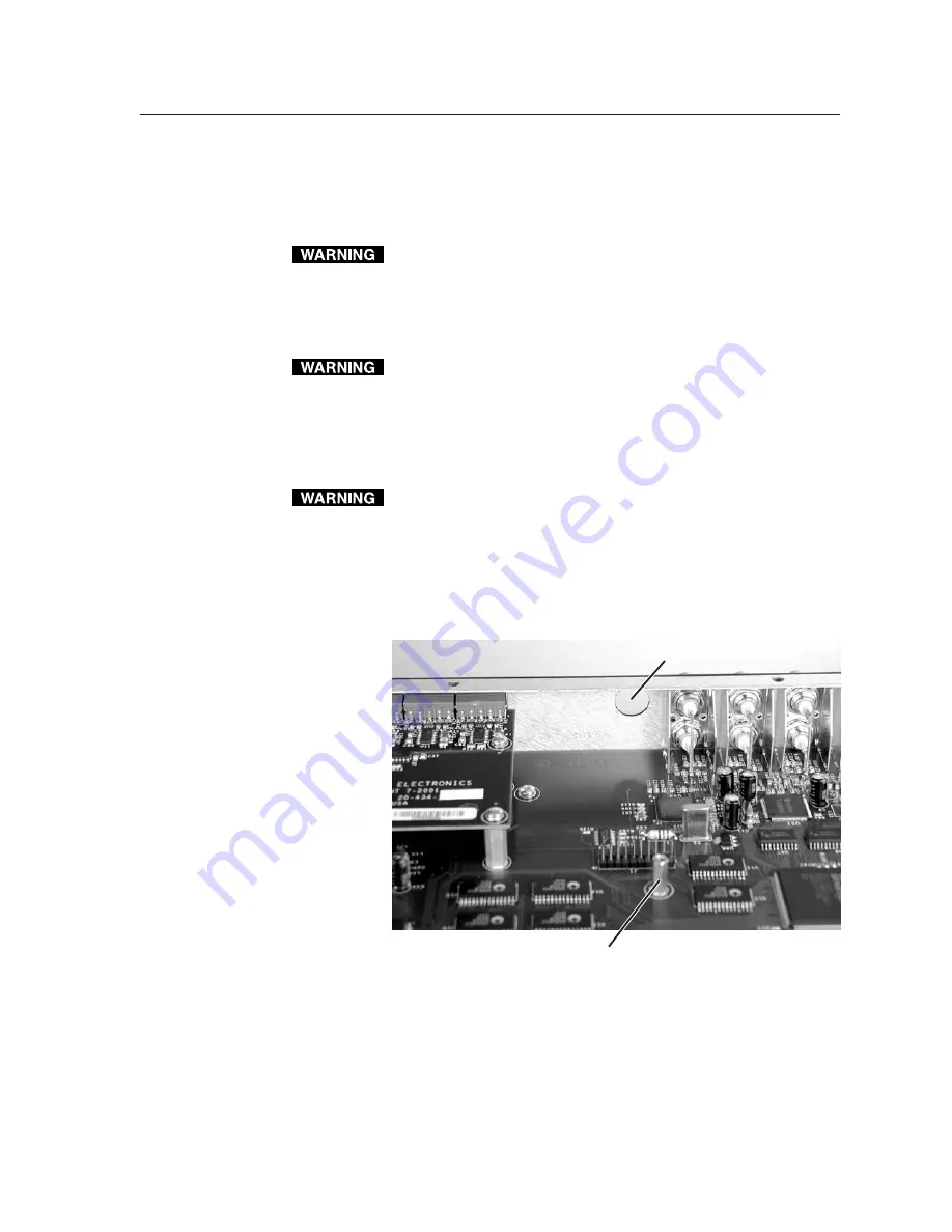
Locate the SDI card standoff located near the middle rear portion of the
main circuit board (looking from above with the front panel nearest to you).

5.

Remove the adhesive SDI cover from the rear SDI connector opening of the
scaler and position the SDI card at an angle with the SDI connector
protruding from the rear SDI connector opening.

6.

The SDI card has a 20-pin socket on the underside which should align with
the 20 pins on the main circuit board.  Be sure to align the pins properly, in
order to prevent bending the pins, before pressing the SDI card firmly in
place against the standoff.  The mounting hole on the SDI card should now
be directly over the standoff.

SDI connector opening

SDI card standoff

Summary of Contents for DVS 406

Page 1: ...DVS 406 Digital Video Scaler Series DVS 406 DVS 406 A DVS 406 D and DVS 406 AD 68 539 01 Rev D 02 05...

Page 2: ...con los equipos Este s mbolo se utiliza para advertir al usuario sobre la presencia de elementos con voltaje peligroso sin protecci n aislante que puedan encontrarse dentro de lacajaoalojamientodelpr...

Page 3: ...t RGBS input HD YUV to RGB PASS THROUGH R G B V H HD YUV to RGB PASS THROUGH R G B H HD YUV to RGB PASS THROUGH R G B V H HD YUV to RGB PASS THROUGH R G B V H V HV HV R Y Y B Y HV R Y Y B Y R Y Y B Y...

Page 4: ...Input 1 video types RGB pass through default YUV pass through Input 2 video types RGB pass through RGBcS YUVi default YUVp Input 3 video types Video default S video Input 4 video types Video default...

Page 5: ...5 Advanced Configuration menu MENU Memory Presets Switch Mode Take Auto NEXT Advanced Configuration Effect Type Cut NEXT Edge Smoothing Off On NEXT Top Blanking Bot 000 000 NEXT RGB Delay 0 0 Seconds...

Page 6: ...GB Pass Through Input 3 S Video 10 sec timeout NOTE The horizontal Adjust knob and the vertical Adjust knob are used to adjust the image settings on the left and right sides of the LCD screen respecti...

Page 7: ...lay and controls 2 8 Optimizing the System 2 8 Setting up a DVD source 2 8 Menus Configuration and Adjustments 2 9 Moving through menus by using front panel controls 2 9 Menu overview 2 9 Input Config...

Page 8: ...32 Programmer s Guide 3 2 Host to scaler communications 3 2 Scaler initiated messages 3 2 Error responses 3 2 Using the command response tables 3 3 Command response table for SIS commands 3 4 Command...

Page 9: ...DVS 406 1 Chapter One Introduction About this Manual About the DVS 406 Features and Options...

Page 10: ...te video and each input is separately configurable Audio versions of the scaler accept six line level balanced or unbalanced stereo audio inputs To enable superior scaling performance the DVS 406 feat...

Page 11: ...vidually set One balanced or unbalanced stereo audio output One line level output is provided on 3 5 mm 5 pole captive screw terminals Audio breakaway Audio and video can be switched separately via RS...

Page 12: ...results in richly detailed images with sharply defined lines A similar process is used for PAL film source video Versatile mounting options The DVS 406 can be rack mounted or it can be placed on a tab...

Page 13: ...allation and Operation Mounting the Scaler Rear Panel Features Front Panel Features Optimizing the System Menus Configuration and Adjustments Image Adjustments Front Panel Lockout IR 901 Infrared Remo...

Page 14: ...ttom of the unit Rack mounting For rack mounting do not install the rubber feet Attach the provided rack mounting brackets to the scaler with machine screws as shown below then fasten the scaler to th...

Page 15: ...ble connections Codec DVD Extron DVS 406 2A MA X 100 24 0V 50 60H z RS 23 2 SD I RG B R Y B Y Y S V IDE O VID EO 6 4 5 3 1 RG B PA SS TH RO UG H R G B V H V R G B H V O U T I N T P U T S R G B H V Vid...

Page 16: ...computer video RGB and component video interlaced and progressive signals The RGBHV RGBS RGsB input signal will be pass through Connect cables for the appropriate signal type as shown here 2A MAX 100...

Page 17: ...ows RGBS RGBHV RGsB Sync on Green RsGsBs output only if input is RsGsBs R G B H HV V R G B H HV V R G B H HV V Both outputs are buffered and can be connected simultaneously to two different displays F...

Page 18: ...connect an audio device such as an audio recorder VCR or powered speakers to this 3 5 mm 5 pole captive screw connector Follow the diagram below for correct wiring Unbalanced Output Tip See Caution S...

Page 19: ...8 Take button When this button is enabled through the menu system selecting an input selection button 2 thru 7 above followed by pressing the Take button will cause a switch to the new input to occur...

Page 20: ...etails 15 Menu button Use this button to enter and move through the main menu system in the DVS 406 See the Menus Configuration and Adjustments section in this chapter for details 16 Next button Use t...

Page 21: ...nd to make adjustment selections Refer to the flowcharts in this chapter and to specific sections for explanations on knob adjustments Image adjustment buttons Col Tnt color tint Brt Cont brightness c...

Page 22: ...p Input 3 video types Video default S video Input 4 video types Video default S video Input 5 video types Video default S video If you press the Menu button while a submenu is active the next main men...

Page 23: ...Video Type 4 and 5 submenu to select the appropriate video format composite video S video for input 5 The default for input 5 is composite video Output Configuration The following flowchart provides...

Page 24: ...80p X X HDTV 576p X X HDTV 720p X X HDTV 1080p X X HDTV 1080i X X X Resolution locked to input 1 Rate is auto selected based on input Default refresh rate The default resolution and rate is 640 x 480...

Page 25: ...audio for the given input Audio Switch When the video input signal is being switched there are four methods for switching the audio Start switches to the next audio input at the beginning of the next...

Page 26: ...select either N A 1 2 or 3 to select a preset The default is N A To save the preset press the NEXT button Clear memory presets From this submenu up to three saved presets for the currently selected i...

Page 27: ...is selected The two effects are cut and dissolve A cut instantaneously switches from one input to another A dissolve causes one input to fade out while fading in another selected input The dissolve e...

Page 28: ...vertical Adjust knob to specify this mode The default is Off Key mode Key mode allows input 1 to be displayed simultaneously with any other selected input The effect resembles two images being display...

Page 29: ...nfiguration menu Extron DVS 406 Output Configuration MENU Input Configuration MENU Audio Configuration MENU Memory Presets MENU Advanced Configuration MENU Exit Menu MENU MENU NEXT 2 sec 2 sec Input 1...

Page 30: ...s to settings press the Col Tnt and Center buttons simultaneously for 2 seconds to lock the DVS 406 s front panel The lock mode locks all front panel functions except input selection and the Take butt...

Page 31: ...om part contains the adjustment controls for color tint brightness contrast detail and sharpness adjustments The adjustment functions will be disabled if the front panel lock mode is on Selecting an i...

Page 32: ...nc adapter such as Extron s ASTA active sync termination adapter may help solve these problems 6 For LCD and DLP projectors and plasma displays In addition to the sync related information above check...

Page 33: ...cted Switch to input 2 6 Input 1 is not active pass through only The image is green The output sync Turn off sync on green is configured for sync on green The image is too soft The detail sharp Change...

Page 34: ...Installation and Operation cont d DVS 406 Installation and Operation 2 22...

Page 35: ...DVS 406 3 Chapter Three Serial Communication RS 232 Programmer s Guide Control Software for Windows...

Page 36: ...the host end with a carriage return and a line feed CR LF which signals the end of the response character string A string is one or more characters It is also possible to send several SIS commands ba...

Page 37: ...il and sharpness upper and lower case characters may be used interchangeably in the command field The ASCII to HEX conversion table at left is for use with the command response tables ASCII to Hex con...

Page 38: ...dB Example 8g Aud 8 0 Example set attenuation to 8 dB View audio channel level G Aud X9 Show an input s audio level Audio mute Mute on 1Z Amt X2 Mute both audio outputs Example 1Z Amt1 Mute off 0Z Am...

Page 39: ...de Set the detail level X13 D Det X13 Specify the detail level View the detail value D Det X13 Show the detail setting Sharpness mode Set the sharpness level X18 d Shp X18 Specify the sharpness level...

Page 40: ...image Disable 0F Frz0 Turn off freeze output motion View the freeze status F Frz X2 Show the freeze status Example F Frz0 Front panel security lockout Disable 0X Exe0 Adjustments selections can be mad...

Page 41: ...econds in 0 1 second steps up to 10 dissolve 1 0 seconds Example 4 3 Eff03 Example 0 3 second dissolve Scaler settings Scaler output sync format 6 X Syn X 0 RGBHV default 1 RGBS 2 RGsB sync on green S...

Page 42: ...EXE from the CD 2 Follow the instructions that appear on the screen By default the installation creates a C DVS 406 directory and it places two icons DVS 406 Control Pgm and DVS 406 Help into a group...

Page 43: ...mputer key or click on the Help menu from within the DVS 406 Control Program or double click on the DVS 406 Help icon in the Extron Electronics group or folder For explanations of buttons or functions...

Page 44: ...Serial Communication cont d DVS 406 Serial Communication 3 10...

Page 45: ...DVS 406 A Appendix Appendix Specifications Part Numbers and Accessories Firmware Upgrade Installation Audio Card Installation Serial Digital Interface SDI Card Installation...

Page 46: ...ideo processing Decoder 9 bit digital Digitalsampling 24 bit 8 bits per color 13 5 MHz interlaced signals 24 bit 8 bits per color 27 MHz 480p signals Colors 16 78 million Video output Number signal ty...

Page 47: ...anced at 1 THD N Input gain adjustment 15 dB to 9 dB adjustable per input via RS 232 or front panel 0 dBu 0 775V 0 dBV 1V 0 dBV 2 dBu Audio output Number signal type 1 stereo balanced unbalanced Conne...

Page 48: ...ered separately Accessories Part number IR 901 remote control 70 152 01 SDI video input card 70 168 01 DVS audio input output card 70 151 01 Enclosure dimensions 1 75 H x 17 5 W x 12 D 1U high full ra...

Page 49: ...ut cables To prevent electric shock always unplug the DVS 406 scaler from the AC power source before opening the enclosure 2 Remove the scaler from the rack or furniture 3 Remove the cover of the scal...

Page 50: ...PLCC IC puller tool with the slots located in opposite ends of the U41 firmware chip 6 Insert the hooks into the slots and squeeze the tool gently to grasp the chip 7 Pull the chip straight out of th...

Page 51: ...the top half of the enclosure by removing the screws then lifting the cover straight up See the top cover removal diagram in the Firmware Upgrade Installation section Do not touch any switches or oth...

Page 52: ...standoffs The four mounting holes on the audio card should now be directly over the standoffs 7 Insert the four installation screws through the audio card s mounting holes and gently tighten them into...

Page 53: ...are Upgrade Installation section Do not touch any switches or other electronic components inside the scaler Doing so could damage the scaler Electrostatic discharge ESD can damage IC chips even though...

Page 54: ...all the SDI connector s hex nut and keep the SDI card from twisting as the nut is tightened 9 Replace the top cover on the DVS 406 scaler and fasten it with the screws that were removed in step 3 10 R...

Page 55: ...t and Central America Extron Electronics Europe ExtronElectronics Beeldschermweg6C 1001 East Ball Road 3821AHAmersfoort Anaheim CA 92805 USA The Netherlands Asia Japan Extron Electronics Asia Extron E...

Page 56: ...tronics Europe Beeldschermweg 6C 3821 AH Amersfoort The Netherlands 31 33 453 4040 Fax 31 33 453 4050 Extron Electronics Asia 135 Joo Seng Road 04 01 PM Industrial Building Singapore 368363 65 6383 44...

Reviews: