background image


5-19

DVCM 50 • Software-based Confi guration and Control

PRELIMINAR

Y


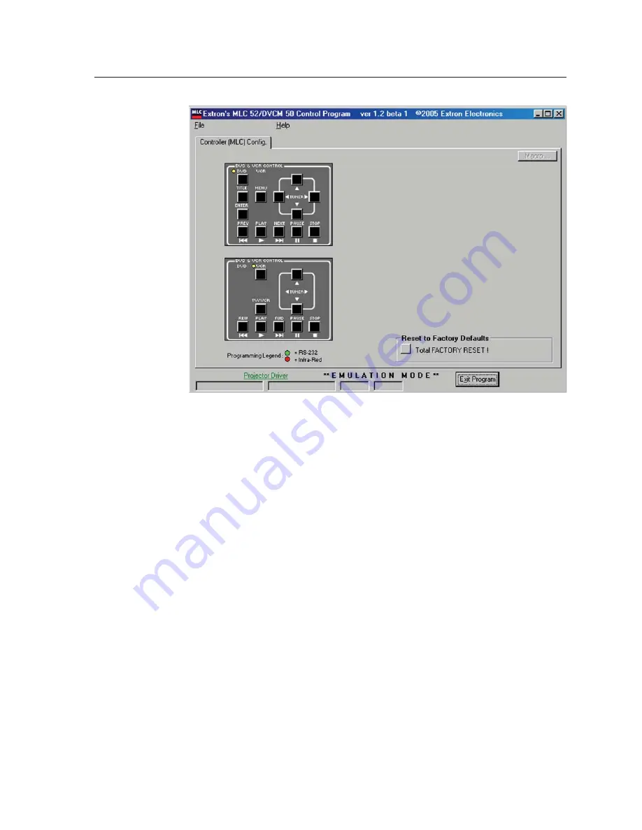
DVCM confi guration program screen in emulation mode

6

Select the desired settings in each section of the program to confi gure the 
buttons, using the same processes described under 

Assigning command 

functions to buttons

, earlier in this chapter.


An exception is that in emulation mode you cannot perform IR Learning.  You 
must have a DVCM connected to the host computer for IR Learning.

7

To save the confi guration emulation for future use, follow steps 

1

 and 

2

 under 

Saving and restoring confi gurations

, earlier in this chapter.

Uploading fi rmware

If the need arises, you can update the DVCM 50’s fi rmware via RS-232.  Visit the 
Extron Web site (www.extron.com), and check for fi rmware updates, which you can 
download.  After you have downloaded the new fi rmware fi le to your PC, follow 
these steps to upload it to your DVCM.

1

Launch the MLC 52/DVCM 50 confi guration software and save the current 
confi guration.  (See 

Saving and restoring the confi guration

, earlier in this 

chapter.)

2

From the File drop-down menu, select Update Firmware... .    

Summary of Contents for DVCM 50

Page 1: ...DVCM 50 DVD VCR Control Module 68 1098 01 Rev A 11 05 ...

Page 2: ...sollten Sie alle Sicherheits und Bedienungsanleitungen genau durchlesen und verstehen Aufbewahren der Anleitungen Die Hinweise zur elektrischen Sicherheit des Produktes sollten Sie aufbewahren damit Sie im Bedarfsfall darauf zurückgreifen können Befolgen der Warnhinweise Befolgen Sie alle Warnhinweise und Anleitungen auf dem Gerät oder in der Benutzerdokumentation Keine Zusatzgeräte Verwenden Sie ...

Page 3: ...ration 3 1 DVD and VCR Control 3 2 Front Panel Components 3 2 Other buttons on the front panel 3 4 Programming the DVCM 50 Using IR 3 4 Configuring using IR Learning 3 5 Programming the DVD and VCR buttons 3 7 Removing commands from a button 3 7 Setting up button macros 3 7 Taking a button out of macro mode 3 8 Configuring using IR data transfer 3 8 Operating the DVCM 50 Using IR Remote Control 3 ...

Page 4: ...verview of the Controller MLC Config tab 5 7 Saving and restoring a configuration 5 8 Saving a configuration 5 8 Restoring a configuration 5 9 Assigning command functions to buttons 5 9 Removing commands from a button 5 12 Setting up button macros using macro mode 5 13 Performing IR Learning via software 5 14 Using emulation mode 5 16 Uploading firmware 5 19 Using Simple Instruction Set SIS Comman...

Page 5: ...PRELIMINARY DVCM 50 DVD VCR Control Module 1 Chapter One Introduction About This Manual About the DVCM 50 DVD VCR Control Module Features Application Diagrams ...

Page 6: ...ach button can be set to send out multiple IR commands A button configured for macro mode can issue up to four commands in sequence from a single button press A button configured for toggle mode can issue up to four different commands sending out a different command each time the button is pressed Front panel configuration port This serial port enables advanced configuration driver downloads and f...

Page 7: ...y be connected DVD VCR Extron AAP 102 Mounting Frame Extron DVCM 50 DVD VCR Control Module IR Emitters AAP 102 DVD VCR CONTROL PL AY NEX T FW D PA USE ST OP TU NER Tx PR EV REW EN TE R TITL E MEN U TV VCR DVD VC R CONFIG DVCM 50 DVCM 50 configured as a standalone control module DVD Projector VCR Extron MLC 104 IP AAP MediaLink Controller RS 232 Control Extron DVCM 50 DVD VCR Control Module IR Emit...

Page 8: ...Introduction cont d DVCM 50 Introduction 1 4 PRELIMINARY ...

Page 9: ...PRELIMINARY DVCM 50 DVD VCR Control Module 2 Chapter Two Installation Installation Overview UL Requirements Mounting the DVCM 50 Rear Panel Features Wiring the Control Connector ...

Page 10: ...or detailed information on the configuration software 6 Test the system press the DVCM s buttons and observe the DVD player and or VCR responses If they are not responding properly ensure that all devices are plugged in and receiving power Check the cabling and make adjustments as needed 7 Optional Mount the DVCM to the wall or furniture as follows a If using the optional external power supply dis...

Page 11: ...mount the device faceplate or AAP wallplate with the DVCM attached onto a wall electrical wall box mounting bracket or furniture following the instructions provided with the mounting option Rear Panel Features 5 4 1 1 2 3 8 4 2 1 E 4 ON 2 3 4 IR OUT GND IR IN GND 12V GND Rx Tx 1 7 6 3 2 DVCM 50 rear panel 1 Configuration switches These DIP switches place the DVCM in IR learning mode or data transf...

Page 12: ...port This 3 5 mm 3 pole captive screw connector located near the lower left corner of the rear panel is used for connecting to the MLC 104 see chapter 4 Special Application for more information on the MLC 104 When the DVCM is operating in standalone mode this port is not used 7 IR Learner Transmitter LEDs The two LEDs one for transmitting one for receiving send and receive IR signals enabling the ...

Page 13: ...ation below DVCM 50 IR control port For the IR Emitter only IR Emitter White striped wire only IR Modulated IR Ground 100 feet 33 5 m maximum Connect up to 2 IR Emitters max E D C B A Connect this end to the IR control window of the DVD or VCR D E Wiring for IR control Wiring for IR remote control An optional IR Link or IRL 20 can be connected to the IR In port to enable the DVCM to receive IR sig...

Page 14: ...ectors are included with the IR Link but the cable must be purchased separately 5 Plug one 5 pole connector into one of the IR Link s communications connectors 6 Plug the other 5 pole connector into the rear panel control port of the DVCM 50 IR Link Rear Panel DVCM 50 Rear Panel 1 1 2 3 8 4 2 1 E 4 ON 2 3 4 IR OUT GND IR IN GND 12V GND Rx Tx GND 12V A B D GND 12 V A B C IR IN Wiring the IR Link fo...

Page 15: ... go between the DVCM and the IRL 20 See appendix A for cable part numbers The maximum total distance between an Extron control module and the IRL 20 is 150 45 m 2 Attach a 3 5 mm 5 pole captive screw connector to the end of the cable that will be plugged into the IRL 20 3 Connect the wires on the other end of the cable to the provided 3 5 mm 5 pole captive screw connector as described below and pl...

Page 16: ... to power the DVCM as shown in the following diagram The power supply is not included with the control module The DVCM 50 can share power with an MLC 104 or MLC 52 Ground 12 VDC input DVCM 50 Control Port E D C B A A B Ground all devices An external power supply 12 VDC 1A max Sold separately Part 70 055 01 Connecting the DVCM 50 to the external power supply Check the power supply s polarity before...

Page 17: ...l Module 3 Chapter Three Configuration and Operation DVD and VCR Control Front Panel Components Programming the DVCM 50 Using IR Operating the DVCM 50 Using IR Remote Control Resetting the DVCM 50 Locking the Front Panel Executive Mode ...

Page 18: ...through IR learning IR learning is convenient for installing new or updated commands into the DVCM in the field It can be performed with or without the use of software A DVCM 50 can transfer configure duplicate or clone its configuration to another DVCM 50 via IR data transfer without the use of cables or software Configurations are stored in non volatile memory Therefore if the power to the unit ...

Page 19: ...n DVD mode 3 VCR indicator LED This LED glows amber when the DVCM is in VCR mode 4 Tx Transmission LED This green LED blinks while the DVCM is transmitting IR commands It also blinks when any programmed front panel button is pressed If a button is held down the Tx LED continues to blink until the button is released If a button that was not programmed is pressed the Tx LED does not blink 5 Configur...

Page 20: ...h between operating as a TV tuner and operating as a VCR This button can be programmed and can issue IR commands only in VCR mode Title DVD mode only Program this button with the IR command that displays the main menu on the display device screen This button can be programmed and can issue IR commands only in DVD mode Enter DVD mode only Program this button with the IR command that selects items f...

Page 21: ... DVD or VCR button to select the mode in which the button will be programmed When you press the DVD or VCR mode button the LED lights above the button that you pressed indicating that the front panel buttons will be programmed for that mode 4 Press the button on the front panel that will store the IR code that you want the DVCM to learn The following takes place on the DVCM rear panel The orange b...

Page 22: ...d 3 learned Command 2 learned Command 1 learned Activation of learning indicator LEDs during button programming 5 Within 5 seconds point the DVD or VCR remote control at the IR learning sensors on the rear panel and press the remote control button whose function you want the selected DVCM button to learn If the IR command is learned successfully the IR Learning indicator LEDs blink in rapid progre...

Page 23: ...ore up to four commands In macro mode a single press of a button issues all the commands up to four that have been programmed on that button in the order they were programmed at 1 5 second intervals An example of a button macro application would be turning on multiple DVDs or VCRs by pressing one button one time To put a button in macro mode follow these steps 1 Ensure that power is applied to the...

Page 24: ...de Then erase the Play function and all other functions from the Play button by pressing it twice within 2 seconds 4 Verify that the button s commands were erased by pressing the button again If the commands have been erased only LED 1 the bottom LED blinks and the other LEDs are off 5 Repeat steps 1 through 3 for any additional buttons that you want to erase When finished place switch 1 in the Of...

Page 25: ...t may take longer if the transmitting unit has multiple commands programmed on each button The button indicator LEDs on the rear panel act as data transfer progress indicators While data is being transferred these LEDs on both the transmitting and the receiving DVCMs light to indicate the amount of data that has been transferred After approximately 25 of the data has been transferred the first LED...

Page 26: ...want to repeat the transfer process to configure another DVCM 50 repeat steps 3 and 4 for the unit that is to be configured Press any button on the transmitting unit The transfer process restarts Operating the DVCM 50 Using IR Remote Control The optional hand held IR 452 Remote Control can be used in conjunction with an optional IR Link or IRL 20 and the DVCM 50 to operate your VCR and or DVD play...

Page 27: ...ignal it receives via the IR In port and responds as if its own equivalent button were pressed issuing the command to the DVD VCR Setup operations on the DVCM 50 cannot be performed from the IR 452 Buttons on the IR 452 remote control The buttons on the optional IR 452 Remote Control duplicate the DVCM 50 s front panel controls for normal operation The DVCM responds to IR signals from the IR 452 a...

Page 28: ...er to the IR 452 User s Manual for more information on using the IR 452 Resetting the DVCM 50 If the need ever arises to reset the DVCM 50 you can use one of the following methods Factory firmware reset Press and hold the Stop button while applying power to the DVCM This method resets the DVCM firmware to the version with which the unit was delivered from the factory Any codes that you previously ...

Page 29: ... that pressing the buttons has no effect To enable executive mode press and hold the Tuner W and X buttons simultaneously for 5 seconds When the DVCM enters executive mode the DVD and VCR LEDs light and remain lit DVD VCR CONTROL TUNER Tx DVD VCR CONFIG DVCM 50 PLAY NEXT FWD PAUSE STOP PREV REW ENTER TITLE MENU TV VCR Buttons for executive mode press and hold for 5 seconds To exit executive mode p...

Page 30: ...Configuration and Operation cont d DVCM 50 Configuration and Operation 3 14 PRELIMINARY ...

Page 31: ...PRELIMINARY DVCM 50 DVD VCR Control Module 4 Chapter Four Special Application Connecting the DVCM 50 to the MLC 104 Input Selection Using the IR 452 to Control the DVCM 50 and the MLC 104 ...

Page 32: ...ounted The combination of these two products is very useful for the following reasons It provides DVD VCR control for an MLC 104 system It provides IR control of the MLC 104 when the DVCM 50 is used with an IR Link or IRL 20 VCR IR SYSTEM REMOTE FRONT PANEL DVD VCR DVD VCR TV VCR VOL VOL PC VIDEO CHANNEL IR 452 CONFIG PROJECTOR VOLUME 1 2 3 4 ON OFF DVD VCR PC IMAGE MUTE Extron MLC 104 IP AAP DVD ...

Page 33: ...o the DVCM s 3 pole host port on the rear panel Connectors are included with the DVCM 50 but the cable must be purchased separately See appendix A for cable part numbers 1 1 2 3 8 4 2 1 E 4 ON 2 3 4 IR OUT GND IR IN GND 12V GND Rx Tx V G SCP 12V OUT PWR SNS GROUND GROUND GROUND GROUND GROUND Tx Rx HOST CONFIG LAN PRESS TAB WITH TWEEKER TO REMOVE A B A B E MLS PWR RS 232 SCP COMM Tx IR Rx Tx Rx 12V...

Page 34: ...ing these buttons activates the DVCM 50 s DVD or VCR buttons which select the input device The DVD and VCR buttons on the DVCM 50 do not need to be specified or programmed to select the DVD or VCR These buttons are preset to switch the system to DVD and VCR mode when pressed and their settings cannot be changed To select the DVD VCR pair of input buttons set configuration DIP switch 4 on the DVCM ...

Page 35: ...the labeling procedure You cannot use the same button for both DVD and VCR when the MLC 104 is connected to a DVCM 50 Buttons 1 or 3 must be used for DVD selection buttons 2 and 4 must be used for VCR selection Buttons 1 and 2 or buttons 3 and 4 must be used together for DVD VCR selection You cannot pair buttons 1 and 4 or buttons 2 and 3 together 3 Set configuration switch 4 on the rear panel to ...

Page 36: ...this chapter 3 Connect the IR Link or the IRL 20 to the DVCM 50 rear panel See Wiring for IR remote control in chapter 2 4 Mount the MLC 104 the DVCM 50 and the IR Link or IRL 20 on a wall or furniture as desired Refer to the mounting instructions in the MLC 104 User s Manual Controlling the MLC 104 with the IR 452 The IR 452 controls the MLC 104 through the IR Link or IRL 20 and the DVCM 50 which...

Page 37: ...f the MLC 104 3 The MLC 104 activates the button on its front panel that is associated with the SIS command it receives When the button is activated the command programmed to it is sent to the projector or display device Buttons and commands used with the MLC 104 To control the MLC 104 you use the buttons in the Display and Front Panel sections of the IR 452 See the illustration below FRONT PANEL ...

Page 38: ...n button in the Display section of the IR 452 the signal sent to the DVCM 50 is interpreted as the SIS command 1P This command is sent to the MLC 104 to activate the button that is labeled On in the Projector section The MLC 104 responds by issuing the command to the projector to turn on Once you have programmed and labeled the buttons on the MLC 104 you should relabel the IR 452 buttons to indica...

Page 39: ... send a V or V SIS command to the MLC 104 which responds by increasing or decreasing the volume on the display device Remove the Volume label from the sheet of labels provided with the IR 452 and affix it above the arrow rocker button on the IR 452 front panel as shown in the illustration below SYSTEM REMOTE FRONT PANEL DVD VCR DVD VCR TV VCR VOL VOL PC VIDEO CHANNEL IR 452 POWER ON VOLUME Labelin...

Page 40: ...Special Application cont d DVCM 50 Special Application 4 10 PRELIMINARY ...

Page 41: ...PRELIMINARY DVCM 50 DVD VCR Control Module 5 Chapter Five Software based Configuration and Control Using the Windows based Configuration Software Using Simple Instruction Set SIS Commands ...

Page 42: ...rity None Using the Windows based Configuration Software Extron s MLC 52 DVCM 50 Control Program Windows based configuration software included with your DVCM 50 provides a convenient way to program all the DVCM buttons in both DVD and VCR mode This configuration program s graphical user interface includes the same functions as those on the DVCM s front panel plus the ability to download IR drivers...

Page 43: ...egabytes total of hard disk space To install the software and IR drivers onto the PC hard drive follow these steps 1 Insert the CD ROM into your CD drive The disk should start automatically If it does not run LAUNCH EXE from the CD 2 On Software Installation screen click Install Program Software Installation screen on the DVCM 50 CD 3 On the File Download window that appears click Run to begin ins...

Page 44: ...nk Drivers 6 Click Run on the File Download window then click Run again on the Security prompt window 7 Follow the instructions on the Driver InstallShield Wizard screens to complete the driver installation By default the installation places a folder called Driver 2 containing the set of IR drivers in the Extron folder under Program Files If your Program Files folder does not contain an Extron fol...

Page 45: ...he DVCM 50 When the software is opened it detects your DVCM 50 connection to the PC and displays the DVCM 50 screen 2 Select the comm port through which your computer will communicate with the DVCM 50 3 Click OK After a few seconds the Extron DVCM 50 configuration program screen appears displaying the Controller MLC Config tab The DVCM 50 screen has only this tab Overview of the DVCM 50 configurat...

Page 46: ...nformation on program features do one of the following to display the context sensitive DVCM 50 online Help From the Help menu on the DVCM 50 configuration program screen select Contents Press the F1 computer key Double click on the MediaLnk52 hlp file in the MediaLink52 folder on your PC hard drive For explanations of buttons or functions click on the tabs in the help screen to reach the desired ...

Page 47: ...ove programming from buttons and configure buttons in toggle and macro modes Overview of the Controller MLC Config tab The DVCM 50 screen contains one tab Controller MLC Config This tab contains graphical representations of the DVCM 50 in DVD mode and in VCR mode When you click on the button representations in these diagrams menus are displayed enabling you to configure the DVCM buttons The Progra...

Page 48: ...RATION as File menu The Save Current MediaLink Configuration as window opens 2 If necessary browse to locate the folder in which you want to save your configuration It is recommended that you save it in the MediaLink folder or in another directory where the file can be found easily 3 Make sure the Save as type field is set to MediaLink Configs MLK 4 Enter a name for the configuration in the File n...

Page 49: ...nfiguration file that you want to restore Configuration files are usually stored in the MediaLink folder 4 Select the desired configuration file It must have a mlk extension 5 Click Open After a few seconds the saved configuration is uploaded to the DVCM 50 Assigning command functions to buttons IR drivers are used to configure the DVCM 50 Each button has four memory blocks that can be programmed ...

Page 50: ...the Pick IR Driver Functions button in the Actions section Pick IR Driver Functions button on Controller MLC Config tab The Driver Selection window is displayed on top of the Controller MLC Config tab 3 In the Driver Selection window make selections in the following list boxes see the illustration on the next page Driver Category Type of product to be controlled This should be a DVD player a VCR o...

Page 51: ... selected memory block On the Driver Selection window the radio button for the command memory block you just programmed is surrounded by a red field This indicates that the block contains an IR command Driver Selection window showing that memory block 1 Cmd 1 contains an IR command On the DVCM DVD diagram a red dot appears on the button you programmed DVD mode diagram showing Menu button programme...

Page 52: ... finished programming commands to the button click Close to close the Driver Selection window Removing commands from a button You can remove either one command from a button or all the button s commands at once 1 Select the button from which you want to remove commands The button becomes gray 2 If you want to remove only one command from the button select the Cmd radio button for the memory block ...

Page 53: ... four commands When a button is in macro mode one press executes all the commands programmed onto that button in the order they were programmed at 1 5 second intervals One example of a button macro application would be pausing multiple DVD players by pressing the Pause button one time Switching to macro mode does not involve the Macro button in the upper right corner of the Controller MLC Config t...

Page 54: ...program command codes to each of the DVCM button s four memory blocks N Buttons must be configures with IR commands before they are placed in macro mode Follow these steps to initiate IR Learning via the configuration program 1 Set configuration DIP switch 1 on the DVCM rear panel to On up See diagram at right 2 Launch the DVCM 50 configuration software 3 On the DVCM 50 DVD or VCR diagram on the C...

Page 55: ...prompting you to do so Set the switch then click OK 6 The following dialog box opens indicating the button to which IR codes will be learned and to allow you to OK or cancel the IR learning process 7 When you are ready to start click OK A Status of IR Learning message area appears beneath the Actions field instructing you to aim the DVD or VCR remote control and press the button whose function you...

Page 56: ...rs If the command was not learned for any reason a prompt appears telling you that the learn failed and giving you the opportunity to retry or cancel 9 Repeat steps 3 through 8 for each button to be set up with IR codes 10 Place configuration DIP switch 1 back in the Off down position All four switches should be down Using emulation mode The DVCM 50 configuration program features an emulation mode...

Page 57: ...ettings or you can base the configuration on an existing setup If you will be creating a brand new configuration click Cancel on the Initialize Emulated MediaLink Configuration from window The emulated system starts out with the DVCM 50 default settings If you want to create a configuration based on an existing configuration file one that was previously saved select the desired configuration ___ M...

Page 58: ...d MediaLink Configuration as window 4 Enter a filename of your choice for storing the configuration settings it must have a mlk extension then click Save The MediaLink EMULATION MODE Configuration dialog box appears as shown below 5 Select DVCM 50 then click OK The DVCM 50 main screen appears with EMULATION MODE at the bottom ...

Page 59: ...earning 7 To save the configuration emulation for future use follow steps 1 and 2 under Saving and restoring configurations earlier in this chapter Uploading firmware If the need arises you can update the DVCM 50 s firmware via RS 232 Visit the Extron Web site www extron com and check for firmware updates which you can download After you have downloaded the new firmware file to your PC follow thes...

Page 60: ...window locate and select the new firmware file Firmware files are extracted to the following location c Program Files Extron Firmware DVCM 50 vxxx s19 where is an alphanumeric character and vxxx is the firmware version number Firmware update files have a s19 extension make sure that the Files of type field is set to s19 Upload file from window 5 Click Open The firmware update file is uploaded to y...

Page 61: ...riage return and a line feed CR LF which signals the end of the response character string A string is one or more characters DVCM initiated messages When a local event such as a front panel or Extron switcher front panel selection or adjustment takes place the DVCM responds by sending a message to the host No response is required from the host The DVCM initiated messages are listed here underlined...

Page 62: ...ters may be used interchangeably in the command field The ASCII to HEX conversion table below is for use with the command response tables ASCII to HEX Conversion Table ASCII to Hex conversion table Symbol definitions CR LF carriage return line feed hex 0D 0A CR carriage return only hex 0D Space E Escape key X Firmware version number X XX format X On off status 0 off disabled 1 on enabled Memory bl...

Page 63: ...rt number 60 754 02 black 60 754 03 white 60 754 05 RAL9010 white View model name 1I 31 49 DVCM 50 Reset Reset all switches to factory default and erase codes E zXXX 1B 7A 58 58 58 0D Zap X Reset all switches and buttons to the factory default and erase any codes programmed by the user Executive mode Disable executive mode 0X 30 58 Exe 0 Disable front panel lockout Enable executive mode 1X 31 58 E...

Page 64: ...Fail LrnOK Initiate IR Learning Time out during IR Learning Retry IR Learning Aim remote at DVCM and press button again IR Learning has failed IR Learning was successful Abort IR Learning 1B D0 0D Lrn Abort Abort IR Learning Activate a memory block segment emulate a button press Activate a memory block 1B D0 D IRSnd Activate trigger a memory block Send the command stored on that block Command resp...

Page 65: ...PRELIMINARY DVCM 50 DVD VCR Control Module A Appendix A Specifications Part Numbers and Accessories Specifications Part Numbers and Accessories ...

Page 66: ...04 or MLC 104 IP or from an optional external power supply External power supply optional 100 VAC to 240 VAC 50 60 Hz external autoswitchable to 12 VDC 1 A regulated Power input requirements 12 VDC 0 05 A Temperature humidity Storage 40 to 158 F 40 to 70 C 10 to 90 noncondensing Operating 32 to 122 F 0 to 50 C 10 to 90 noncondensing Rack mount Yes with optional rack mounting kit and also wall and ...

Page 67: ... connector 10 319 10 3 pole 3 5 mm captive screw connector 10 265 03 Accessories These items can be ordered separately Adapters power supplies and faceplates Part number 12 VDC 1 amp external power supply 70 055 01 9 DB female 2 5 mm TRS configuration cable 70 335 01 AAP 102 mounting frame black white or RAL9010 white 60 300 02 03 05 MLM 104 LAAP black white or RAL9010 white 70 357 22 23 25 Contro...

Page 68: ...Specifications Part Numbers and Accessories cont d DVCM 50 Specifications Part Numbers and Accessories A 4 PRELIMINARY ...

Page 69: ...and Central America Extron Electronics Europe Extron Electronics Beeldschermweg 6C 1001 East Ball Road 3821 AH Amersfoort Anaheim CA 92805 USA The Netherlands Asia Japan Extron Electronics Asia Extron Electronics Japan 135 Joo Seng Road 04 01 Kyodo Building PM Industrial Bldg 16 Ichibancho Singapore 368363 Chiyoda ku Tokyo 102 0082 Japan This Limited Warranty does not apply if the fault has been c...

Page 70: ...rsfoort The Netherlands 31 33 453 4040 Fax 31 33 453 4050 Extron Electronics Asia 135 Joo Seng Road 04 01 PM Industrial Building Singapore 368363 65 6383 4400 Fax 65 6383 4664 Extron Electronics Japan Kyodo Building 16 Ichibancho Chiyoda ku Tokyo 102 0082 Japan 81 3 3511 7655 Fax 81 3 3511 7656 www extron com 2005 Extron Electronics All rights reserved ...

Reviews: