background image

Operation, cont’d

Digital Display Scaler • Operation

3-4

13

Adjust   (vertical) knob — 

The Adjust   knob changes settings when used in

conjunction with the picture adjustment buttons or the menu system.  Rotate
this knob to change picture settings when one of the picture adjustment
buttons is selected.  In the menu system, rotate this knob to scroll through
menu options and make adjustments.

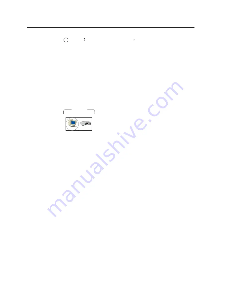
Button icons

The translucent covers on the push buttons can be removed and replaced to insert
labels behind the covers.

Input and output labels can be created easily with Extron’s Button Label Generator
software, which ships with every Extron DDS 402.  Each input and output can be
labeled with names, alphanumeric characters, or even color bitmaps for easy and
intuitive input and output selection (figure 3-2).  See chapter 5, Scaler Software, for
details on using the label software.  See Appendix A, Reference Information, for blank
labels and procedures for removing and replacing the translucent covers.

DVD

Computer

INPUTS

RGB

RGB

R-Y, B-Y, Y

Figure 3-2 — Sample button icons

Front Panel Operations

The following paragraphs detail the power-up process and then describe the menu
system, the picture adjustments, and selection of executive mode.

Power

Power is automatically applied when the power cord is connected to an AC source.
When AC power is applied, the scaler performs a self-test that lights all of the front
panel button indicators and then defaults to the selected input (lit).  The Menu and
Next buttons also light.  The self-test also displays the model name and the
firmware version in the LCD display.  After approximately 2 seconds, the LCD
reverts to its default display, cycling through displays of the selected input, the
input rate, and the selected output rate (figure 3-3).  An error-free power up self-test
sequence leaves all of the button indicators, with the exception of the selected input,
Menu, and Next pushbuttons, unlit and the LCD displaying the default display cycle.

The selected input, the picture adjustments, and other current settings are saved in
non-volatile memory.  When power is applied, the latest configuration is retrieved.

If an error occurs during the self-test, the switcher locks up and will not operate.  If
your switcher locks up on power-up, call the Extron S

3

 Sales & Technical Support

Hotline.

Menu system overview

Figure 3-4 shows a flowchart of the main menus in the menu system.

Menu button — 

Press the Menu button to activate the menu system and to scroll

through the five main menus.

Next button — 

Press the Next button to move between the submenus of a selected

main menu and to activate one for viewing or configuration.  Pressing the
Next button while in the input configuration menu causes the current input’s
number and format type to be displayed on the LCD.

im Vertrieb von

            CAMBOARD Electronics

www.camboard.de

Tel. 07131 911201
Fax 07131 911203

[email protected]

Summary of Contents for DDS 402

Page 1: ...DDS 402 Digital Display Scaler 68 555 01 Rev D 01 05 im Vertrieb von CAMBOARD Electronics www camboard de Tel 07131 911201 Fax 07131 911203 ce info camboard de ...

Page 2: ...tes gefährliche Spannungen die nicht isoliert sind und die einen elektrischen Schock verursachen können herrschen Achtung Lesen der Anleitungen Bevor Sie das Gerät zum ersten Mal verwenden sollten Sie alle Sicherheits und Bedienungsanleitungen genau durchlesen und verstehen Aufbewahren der Anleitungen Die Hinweise zur elektrischen Sicherheit des Produktes sollten Sie aufbewahren damit Sie im Bedar...

Page 3: ... Component video R Y B Y Y S S H V R R Y G Y B B Y R R Y G Y B B Y V H S R R Y G Y B B Y The two video output connectors the 15HD connector and the five BNC connectors both output the same video signal and the same sync format Step 5 Plug the DDS 402 and input and output devices into a grounded AC source and turn on the input and output devices The figure on the following page shows a typical appl...

Page 4: ... 768 60 Main menu Display Cycle MENU MENU 2 sec Power on 2 sec MENU 10 sec MENU 10 sec MENU 10 sec MENU 10 sec 10 sec NEXT 1 2 4 3 5 Output Configuration Input Configuration Memory Presets Advanced Configuration Exit Menu Extron 60 426 01 DDS 402 Version x xx 1 Input menu Menu Next Input video type RGB Betacam 50 YUVi Betacam 60 YUVp HDTV The selected input is also available for the pixel phase ad...

Page 5: ...x 0 0 8 X X X X 4 2 6 x 2 3 8 X X X 0 8 4 x 8 4 8 X X 0 8 4 x 2 5 8 X X 8 6 7 x 4 2 0 1 X X X X X 8 6 7 x 0 8 2 1 X X 4 2 0 1 x 0 8 2 1 X X X 5 6 7 x 0 6 3 1 X X 4 2 0 1 x 5 6 3 1 X X 0 5 0 1 x 0 0 4 1 X X X p 6 7 5 X X p 0 2 7 y l n o z H 0 6 V T D H X X p 0 8 0 1 y l n o z H 0 6 V T D H X X i 0 8 0 1 X X X t u p n i e h t n o d e s a b d e t c e l e s o t u a s i e t a r t u p t u o e h T 3 Memo...

Page 6: ...Top Blanking Bot 000 000 Press and Hold FREEZE to Reset RGB Delay 0 7 Seconds Advanced Configuration MENU Exit Menu Test Pattern Off Edge Smoothing OFF ON Blue Mode OFF ON 5 Exit menu MENU MENU NEXT Display Cycle Advanced Configuration Input Configuration Exit Menu Picture Adjustments menu 10 sec timeout NOTE The Adjust knob and the Adjust knob are used to adjust the image settings on the left and...

Page 7: ...ntrols and Indicators 3 2 Freeze button 3 2 Input buttons 3 2 Selecting an input 3 2 Recalling presets 3 2 Picture adjustment buttons 3 3 LCD display 3 3 Menu control buttons 3 3 Adjustment knobs 3 3 Button icons 3 4 Front Panel Operations 3 4 Power 3 4 Menu system overview 3 4 Configuration 3 5 Input Configuration menu 3 5 Input 2 submenu 3 6 Pixel Phase submenu 3 6 Output Configuration menu 3 6 ...

Page 8: ...er up 4 3 Input selection 4 3 Input and output video type 4 3 Freeze 4 3 Picture adjustments 4 3 RGB delay 4 4 Test pattern 4 4 Presets 4 4 Host to Scaler Instructions 4 5 Scaler Error Responses 4 5 Using the Command Response Table 4 5 Command response table for SIS commands 4 6 Command response table for special function SIS commands 4 9 Chapter 5 Scaler Software 5 1 Control Software for Windows ...

Page 9: ... 1 Specifications A 2 Part Numbers A 3 Included parts A 3 Suggested part A 3 Firmware Upgrade Installation A 4 Button Labels A 6 Installing labels in the scaler s buttons A 6 im Vertrieb von CAMBOARD Electronics www camboard de Tel 07131 911201 Fax 07131 911203 ce info camboard de ...

Page 10: ...ts Table of Contents cont d 68 555 01 Rev D 01 05 All trademarks mentioned in this manual are the properties of their respective owners im Vertrieb von CAMBOARD Electronics www camboard de Tel 07131 911201 Fax 07131 911203 ce info camboard de ...

Page 11: ...Digital Display Scaler 1 Chapter One Introduction About this Manual About the Scaler Features im Vertrieb von CAMBOARD Electronics www camboard de Tel 07131 911201 Fax 07131 911203 ce info camboard de ...

Page 12: ...as both RGBHV or RGBS video and HD component video on five BNCs and a 15HD connector Several of the output resolutions and rates include Extron s Accu RATE Frame Lock AFL a proprietary technology that locks the output frame rate to the input rate solving the problems that result from different input and output rates For home theaters the DDS 402 features HDTV 720p 1080p and 1080i outputs Extron DD...

Page 13: ...nputs The DDS 402 switches between two inputs Input 1 accepts computer video on a 15HD connector Input 2 accepts high resolution RGBHV RGBS RGsB or component video on five BNCs Computer video loop through connector The computer video input Input 1 is buffered looped through and output for use on a local monitor on a 15HD connector Outputs The DDS 402 scales images to the following output resolutio...

Page 14: ...ted from film When film is converted to NTSC video the film frame rate has to be matched to the video frame rate in a process called 3 2 pulldown Jaggies and other image artifacts can result if conventional deinterlacing techniques are used on film source video The DDS 402 s advanced film mode processing recognizes signals that originated from film The DDS 402 then applies video processing algorit...

Page 15: ...tness is saved Front panel security lockout Locks out all front panel functions except the input selection and centering controls When the front panel is locked all functions are still available via RS 232 commands Mounting flexibility Mounting brackets make the 1U high scaler mountable in any conventional 19 wide rack or under or through a desk or other furniture Power The 100VAC to 240VAC auto s...

Page 16: ...Introduction cont d Digital Display Scaler Introduction 1 6 im Vertrieb von CAMBOARD Electronics www camboard de Tel 07131 911201 Fax 07131 911203 ce info camboard de ...

Page 17: ...er 2 Chapter Two Installation Installation Overview Mounting the Scaler Cabling and Rear Panel Views Configuration im Vertrieb von CAMBOARD Electronics www camboard de Tel 07131 911201 Fax 07131 911203 ce info camboard de ...

Page 18: ... this chapter Mounting the Scaler The DDS 402 comes with rubber feet and a set of rack mounting brackets Tabletop use For tabletop use attach a self adhesive rubber foot to each corner of the bottom of the DDS 402 scaler Rack mounting Rack mount the scaler as follows 1 Attach the rack mount brackets to the scaler with eight 8 machine screws provided figure 2 1 2 Insert the scaler into the rack ali...

Page 19: ...component video R Y Y B Y for YUVi or YUVp or Betacam to these female BNC connectors figure 2 3 Ensure that the correct Input 2 video format is selected from the front panel menu see Input 2 submenu in chapter 3 Operation or via the RS 232 port see chapter 4 Programmer s Guide and chapter 5 Scaler Software R R Y G Y B B Y R R Y G Y B B Y H HV V H HV V R R Y G Y B B Y H HV V RGBHV video RGBS video ...

Page 20: ...Scaler Software to install and use the control software Contact closure connection 6 Remote port The Remote connector also provides a way to select an input using a remote contact closure device Contact closure control uses pins on the Remote connector that are not used by the RS 232 interface figure 2 5 To select a different input number using a contact closure device momentarily short the pin fo...

Page 21: ...caler 3 Chapter Three Operation Front Panel Controls and Indicators Front Panel Operations Optimizing the Video im Vertrieb von CAMBOARD Electronics www camboard de Tel 07131 911201 Fax 07131 911203 ce info camboard de ...

Page 22: ...s unlit state Input buttons Each input button selects an input to scale and output The buttons also select memory presets The presets up to three for each input are stored values of the user selectable centering and sizing settings The Input 2 video format resolution and frequency must be identified using either the front panel menus the SIS or the Windows Control program See Front Panel Operation...

Page 23: ...ol button The Zoom button selects and deselects the display zoom adjustment Zoom works the centering and sizing functions simultaneously to enlarge a portion of the displayed image Turning either Adjust knob clockwise zooms in on the image and turning either knob counterclockwise zooms out from the image See Picture adjustments in this chapter 8 Detail control button The Detail button selects and ...

Page 24: ...ler performs a self test that lights all of the front panel button indicators and then defaults to the selected input lit The Menu and Next buttons also light The self test also displays the model name and the firmware version in the LCD display After approximately 2 seconds the LCD reverts to its default display cycling through displays of the selected input the input rate and the selected output...

Page 25: ...e flowcharts in this chapter and to specific sections for explanations on knob adjustments From any menu or submenu after ten seconds of inactivity the DDS 402 saves all adjustment settings and times out to the default LCD display cycle Configuration The DDS 402 can be configured using either the menu system and front panel controls the SIS or the Windows Control program See chapter 4 Programmer s...

Page 26: ...enu displays and lets you set the pixel phase for the selected input Pixels phase is the timing of the digital scaler s sampling Sampling at the optimum pixel phase reduces noise and results in a clear and sharp image Rotate either the Adjust or the Adjust knob to select the pixel phase for the selected input from 0 to 31 You can select the unselected input while this screen is active by pressing ...

Page 27: ...8 z H 0 6 0 5 t a k c o L 0 8 4 x 0 4 6 X X X X 0 0 6 x 0 0 8 X X X X 4 2 6 x 2 3 8 X X X 0 8 4 x 8 4 8 X X 0 8 4 x 2 5 8 X X 8 6 7 x 4 2 0 1 X X X X X 8 6 7 x 0 8 2 1 X X 4 2 0 1 x 0 8 2 1 X X X 5 6 7 x 0 6 3 1 X X 4 2 0 1 x 5 6 3 1 X X 0 5 0 1 x 0 0 4 1 X X X p 6 7 5 X X p 0 2 7 y l n o z H 0 6 V T D H X X p 0 8 0 1 y l n o z H 0 6 V T D H X X i 0 8 0 1 X X X t u p n i e h t n o d e s a b d e t ...

Page 28: ...ring and sizing settings are saved in non volatile memory when the DDS 402 is powered down and later powered back up the settings are available for selection Saving the settings to a preset overwrites the settings previously written to that preset The centering and sizing adjustments are tailored for the selected output rate If you change the output rate and then recall a preset for the earlier ra...

Page 29: ...nd off Blue mode is helpful in the setup of the connected displays monitors In the blue mode only the sync and blue video signals are passed to the display Use either the Adjust knob or the Adjust knob to select On or Off the default Test Pattern submenu The Test Pattern submenu selects from among several test patterns The test patterns are helpful when adjusting the connected displays for color c...

Page 30: ...n the LCD screen Adjustments can then be made by rotating the Adjust knob or the Adjust knob Picture adjustment settings are stored in non volatile memory when the scaler is powered down and powered up the settings are restored Adjust an image for centering sizing brightness contrast color tint zoom or detail as follows figure 3 10 10 sec timeout NOTE The Adjust knob and the Adjust knob are used t...

Page 31: ...djusts from 0 to 7 The DDS 402 picture adjustment functions time out after 10 seconds the adjustments are activated and saved and the LCD returns to the default display cycle 3 Repeat steps 1 and 2 for each image adjustment to be made for that input Front panel security lockout executive mode The front panel security lockout limits the operation of the Digital Display Scaler from the front panel W...

Page 32: ...Use the DSS s size and center functions to fill the crop or aspect ratio test pattern If the input source is a DVD set the DVD player to output a 16 9 aspect ratio see Setting up a DVD source below before sizing the image using the DSS s size function to correct the aspect ratio When sizing and centering a letterbox movie video source increasing the brightness on the DDS makes it easier to see the...

Page 33: ...es Host to Scaler Instructions Scaler Error Responses Using the Command Response Table Command Response Table for SIS Commands Command Response Table for Special Function SIS Commands im Vertrieb von CAMBOARD Electronics www camboard de Tel 07131 911201 Fax 07131 911203 ce info camboard de ...

Page 34: ...acam 60 2 YUVp 5 HDTV X3 Scaler resolution 00 640x480 08 1360x765 01 800x600 09 1365x1024 02 832x624 10 1400 x 1050 03 848x480 11 576p 04 852x480 12 720p 05 1024x768 13 1080p 06 1280x768 14 1080i 07 1280x1024 X4 Scaler refresh rate 00 50 Hz 03 75 Hz 01 56 Hz 04 85 Hz 02 60 Hz 05 Lock 1280 x 768 only Lock is Accu RATE Frame Lock AFL 50 Hz PAL or 59 94 Hz NTSC X5 Output video type 00 RGB 01 Componen...

Page 35: ...X1 is the input number Input and output video type TypX2 A front panel input 2 video type selection has occurred X2 is the input video type Rte X3 X4 A front panel output video format selection has occurred X3 is the output resolution and X4 is the output refresh rate TpoX5 A front panel output video type selection has occurred X5 is the output video format RGB or component Y R y B y Pol X6 A fron...

Page 36: ...blanking adjustment has occurred X11 is the blanking variable X1 Phs X12 A front panel pixel phase adjustment has occurred X1 is the input number and X12 is the pixel phase variable Blu X7 The blue only mode has been turned on or off from the front panel X7 is the on off status Fil X7 The edge enhancement mode has been turned on or off from the front panel X7 is the on off status RGB delay Dly X13...

Page 37: ... the scaler returns an error response to the host The error response codes are E01 Invalid input channel number too large E10 Invalid command E11 Invalid preset number too large E13 Invalid value out of range E17 Illegal command for this signal type Using the Command Response Table The command response table begins on the next page Except for the horizontal and vertical filter settings upper or lo...

Page 38: ... 800x600 at 60 Hz Brightness Set a specific value X8 Y Brt X8 Specify the brightness adjustment Increment Y Brt X8 Increase the brightness Decrement Y Brt X8 Decrease the brightness View the brightness value Y X8 Show the brightness setting Contrast Set a specific contrast value X9 Con X9 Specify the contrast adjustment Increment Con X9 Increase the contrast Decrement Con X9 Decrease the contrast ...

Page 39: ...ng value X11 Blb X11 Example 5 Blb5 Blank bottom five lines Increment bottom blanking value Blb X11 Increase blanking value 1 line Decrement bottom blanking value Blb X11 Decrease blanking value 1 line View the bottom blanking value X11 Pixel phase Set a specific pixel sampling phase X1 X12 U X1 Phs X12 Specify the pixel sampling phase Example 1 11U 1Phs11 Set the sample phase value to 11 for inpu...

Page 40: ...tion requests Query firmware version number Q x xx Show the controller firmware version Request part number N 60 426 01 Show the DDS 402 s part Request general information I See below Show the DDS 402 s status Vid X1 Hrt X16 Vrt X16 Std X17 Prennn In the response the Pre field consists of three digits each of which represents one of the three user presets A one 1 in a digit indicates that a preset...

Page 41: ... host Delay times RGB delay Triple Action Switching 3 X13 Dly X13 Adjustable in 0 01 second steps up to 50 5 0 seconds 0 0 0 seconds default 1 0 1 seconds 2 0 2 seconds and so on Example 3 35 Dly35 RGB delay set to 3 5 seconds Scaler settings Output signal 6 X5 Tpo X5 0 RGB default 1 Component Y R y B y Example 6 1 Tpo01 RGB output signal Output polarity 7 X6 Pol X6 0 H V default 1 H V 2 H V 3 H V...

Page 42: ...Programmer s Guide cont d Digital Display Scaler Programmer s Guide 4 10 im Vertrieb von CAMBOARD Electronics www camboard de Tel 07131 911201 Fax 07131 911203 ce info camboard de ...

Page 43: ...al Display Scaler 5 Chapter Five Scaler Software Control Software for Windows Button Label Generator im Vertrieb von CAMBOARD Electronics www camboard de Tel 07131 911201 Fax 07131 911203 ce info camboard de ...

Page 44: ...ear on the screen The program occupies approximately 2 Mb megabytes of hard drive space By default the installation creates a C USPDDS directory and it places three icons USPDDS Control Pgm USPDDS Help and Button Label Generator into a group or folder named Extron Electronics Using the control program Many items found in the USPDDS Control Program are also accessible via front panel controls and t...

Page 45: ... or click on the Help menu from within the USPDDS Control Program or double click on the USPDDS Help icon in the Extron Electronics group or folder For explanations of buttons or functions click on the tabs in the help screen to reach the desired screen Use a mouse or the Tab and Enter keys to select a button function A description and tips on using the program appear on screen im Vertrieb von CAM...

Page 46: ...To run the Button Label Generator program double click on the Button Label Generator icon shown at right in the Extron Electronics group or folder and click OK when prompted The Extron s Button Label Generator window appears figure 5 3 2 Under System selection choose System 7SC This selection creates the correctly sized labels for the DDS s buttons The button label editing area changes to reflect ...

Page 47: ...caler A Appendix A Reference Information Specifications Part Numbers Firmware Upgrade Installation Button Labels im Vertrieb von CAMBOARD Electronics www camboard de Tel 07131 911201 Fax 07131 911203 ce info camboard de ...

Page 48: ...ponent Y R Y B Y on 15 pin HD 1 RGBHV RGBS HD component Y R Y B Y on BNCs Connectors 1 15 pin HD female 6 BNC female 1 15 pin HD female buffered local monitor output Nominal level 1 Vp p for Y of component video 0 7 Vp p for RGB and for R Y and B Y of component video Minimum maximum levels 0 0 V to 1 0 Vp p Impedance 75 ohms Scaled VGA resolution 640x480 800x600 832x624 848x480 852x480 1024x768 12...

Page 49: ...ide 4 4 cm H x 44 4 cm W x 30 5 cm D Product weight 6 3 lbs 2 9 kg Shipping weight 11 lbs 5 kg Vibration ISTA 1A in carton International Safe Transit Association Listings UL CUL Compliances CE FCC Class A MTBF 30 000 hours Warranty 3 years parts and labor All nominal levels are at 10 Specificationsaresubjecttochangewithoutnotice Part Numbers Included parts These items are included in each order fo...

Page 50: ... the top half of the enclosure by removing the 13 screws 7 on the top and 3 on each side then lifting the cover straight up figure A 1 DDS 402 DI GI TA L DI SP LA Y SC AL ER AD JU ST MEN U 1 2 NE XT PICT UR E AD JU ST MEN TS CE NT ER SIZE BR T CO NT ZO OM IN PU TS RG B FR EE ZE RG B R Y B Y Y DE TA IL Lift Cover Straight Up Remove 13 screws from top and sides Figure A 1 Removing the DDS 402 cover ...

Page 51: ...entation as the old chip Gently but firmly press the chip into place in the socket 10 For U60 or U24 note the key angled corner of the new firmware IC and the dot on the underside that indicates pin 1 figure A 3 Orient the IC to match the key and pin 1 indicated by arrow on the socket and gently but firmly press the IC into place Key Pin 1 mark Pin 1 mark Socket IC Key Figure A 3 Key and pin 1 mar...

Page 52: ...the blanks in figure A 4 or the Button Label Generator software see the chapter 5 Scaler Software Cut them out 2 Remove the button from the scaler by grasping the button firmly and pulling it away from the front panel 3 Use a Tweeker to gently lever the button cap off of the white backing plate 4 Insert a button label into the cap and gently but firmly press the cap onto the white backing plate 5 ...

Page 53: ...ics Europe 1001 East Ball Road Beeldschermweg 6C Anaheim CA 92805 USA 3821 AH Amersfoort The Netherlands Asia Japan Extron Electronics Asia Extron Electronics Japan 135 Joo Seng Road 04 01 Kyodo Building PM Industrial Bldg 16 Ichibancho Singapore 368363 Chiyoda ku Tokyo 102 0082 Japan This Limited Warranty does not apply if the fault has been caused by misuse improper handling care electrical or m...

Page 54: ...4050 Extron Electronics Asia 135 Joo Seng Road 04 01 PM Industrial Building Singapore 368363 65 6383 4400 Fax 65 6383 4664 Extron Electronics Japan Kyodo Building 16 Ichibancho Chiyoda ku Tokyo 102 0082 Japan 81 3 3511 7655 Fax 81 3 3511 7656 www extron com 2005 Extron Electronics All rights reserved im Vertrieb von CAMBOARD Electronics www camboard de Tel 07131 911201 Fax 07131 911203 ce info cam...

Reviews: