4
DTP2 CrossPoint 82 • Setup Guide (Continued)
Front Panel Overview
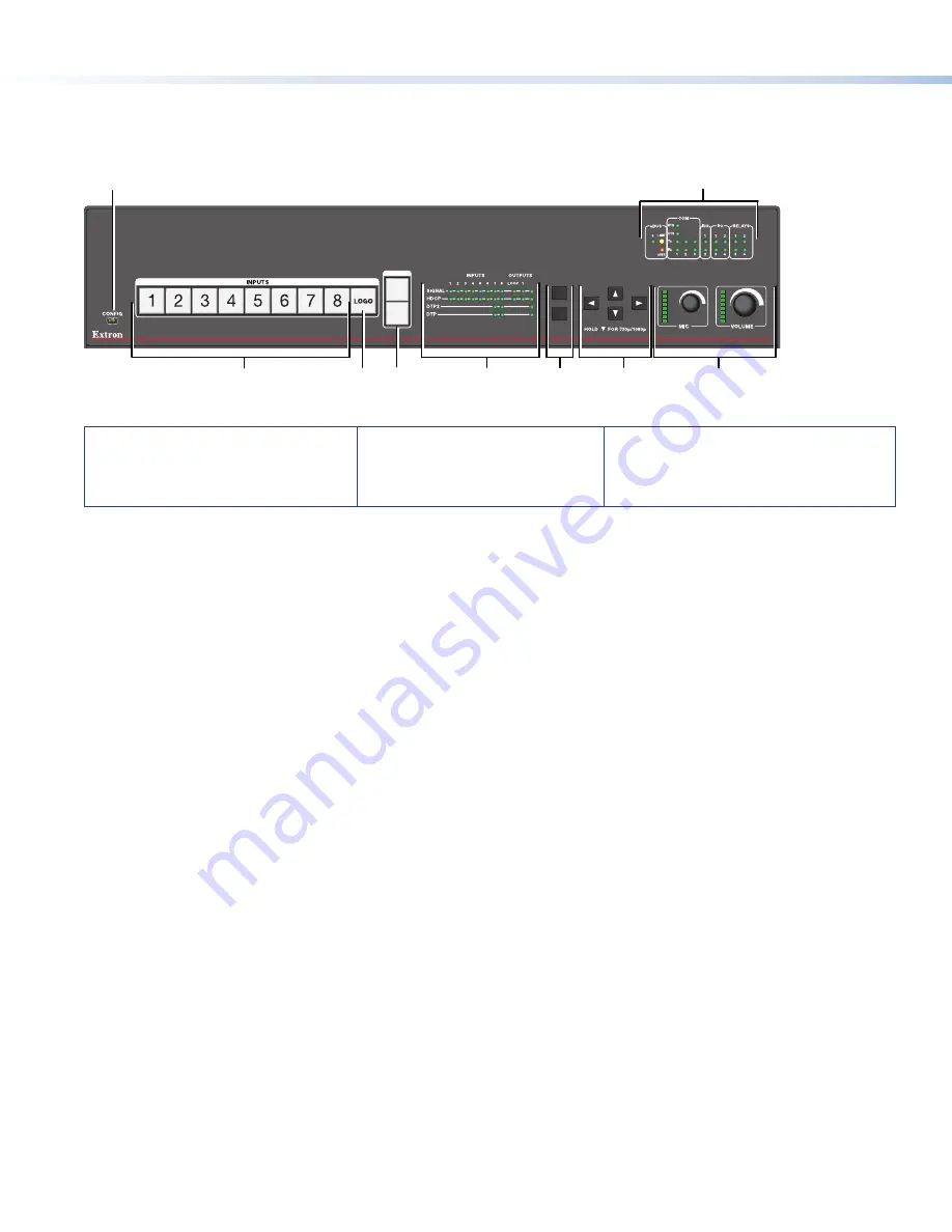
Figure 2 shows the front panel of the DTP2 CrossPoint 82 IPCP SA and IPCP MA 70. The DTP2 CrossPoint 82 base model is 1U
high and has no IPCP Pro LEDs (
I
).
ENTER
MENU
1
2
OUTPUTS
DTP2 CROSSPOINT 82
DIGITAL PRESENTATION MATRIX
2
A
B
F
G
I
H
C
E
D
Figure 2.
Front Panel Features, DTP2 CrossPoint 82 IPCP SA and DTP2 CrossPoint 82 IPCP MA 70
A
Config port
B
Input selection buttons (1 through 8)
C
Logo
button
D
Output selection buttons
E
Signal and Status LEDs
F
Menu
and
Enter
buttons
G
Navigation buttons
H
Mic
and
Volume
knobs and LEDs
I
IPCP Pro LEDs (IPCP models only)
A
Front panel configuration port
— Connect a host device to the USB mini-B port for device configuration, control, and
firmware upgrades.
B
Input selection buttons
(1 through 8) — Press one of these buttons to select an input. The buttons light amber for audio
and video, green for video only, or red for audio only.
C
Logo button
— Selects a logo slot to be displayed on the scaled DTP2 output (not available on the HDMI output).
1.
Press and hold the button until the buttons light for the inputs to which a logo has been assigned.
2.
Press the button for the input with the desired logo (
1
through
8
, slots 9-16 are available via SIS commands only).
See the
DTP2 CrossPoint 82 User Guide
at
or the
DTP2 CrossPoint 82 Help File
for more information
about adding and selecting logos.
D
Output selection buttons
(1 and 2) — Press one of these buttons to select the output on which the selected input is
displayed. Button 1 selects HDMI output 1, which is
not
scaled. Button 2 selects DTP2/XTP/HDBT output 2, which is scaled.
These buttons can select different inputs to display on the two outputs or they can select the same input for both outputs.
E
Status LED indicators
•
Input signal LEDs
— Eight LEDs light green for their corresponding inputs when active video content is detected on
that input.
•
Output signal LEDs
— Output LEDs 1, 2, and Loop light green when the output is connected to a display, and blink
amber when output video and sync are disabled.
•
Input HDCP LEDs
— Eight LEDs light green for each input signal that is HDCP-encrypted.
•
Output HDCP LEDs
— Three LEDs light green for an output when it is currently HDCP-encrypted.
•
DTP and DTP2 Input LEDs
— Two LEDs light green if DTP or DTP2 power is enabled on the corresponding input.
•
DTP and DTP2 Output LEDs
— Two output LEDs light green if DTP or DTP2 power is enabled on DTP2 output 2.
F
Menu and Enter buttons
— Press these buttons to access and navigate the on-screen display menu system (scaled DTP2
output only, not available on the HDMI output).
G
Navigation buttons
— Press these buttons to navigate through the on-screen display menu system or change settings
(scaled DTP2 output only, not available on the HDMI output).
H
Mic and
Volume knobs and LED indicators
— Rotate the
Mic
knob to adjust the microphone level. Rotate the
Volume
knob to adjust the program or output volume level (configurable, see the
DTP2 CrossPoint 82 Help File
for more information).
The eight LED indicators for each knob light according to the level being adjusted. The LEDs light in order from bottom to top
to indicate steps from 1% (-99 dB) to 99% (-1 dB). The bottom LED blinks when the volume is muted. The top LED blinks
when the volume is at 100% (12 dB).
I
IPCP Pro LED indicators
— IPCP models only (see the
IPCP Pro Series Setup Guide
for details).


