background image

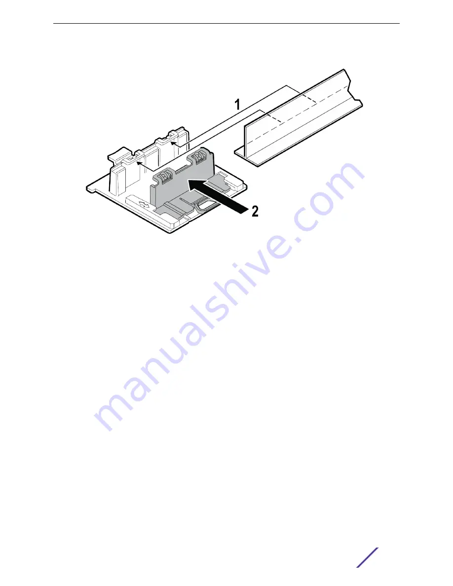
2 Open the movable sliding part of the T-bar to give the stationary and slider T-bar more space.

Figure 5: Installing the T-bar adaptor

3 Hook the stationary end of the T-bar bracket onto the T-bar.
4 Tilt the T-bar up slightly in such a way that you are holding the stationary and movable sides of the

bracket. 4 Squeeze the bracket parts together until you hear the T-bar locking tab click into place.

Installation Process

ExtremeWireless™ AP3915i FCC/ROW Installation Guide

14

Summary of Contents for ExtremeWireless WS-AP3915i-FCC

Page 1: ...ExtremeWireless AP3915i FCC ROW Installation Guide 9035129 Published September 2017 ...

Page 2: ...mes including any product names mentioned in this document are the property of their respective owners and may be trademarks or registered trademarks of their respective companies owners For additional information on Extreme Networks trademarks please see www extremenetworks com company legal trademarks Software Licensing Some software files have been licensed under certain open source or third pa...

Page 3: ...to a Junction Gang box 13 Mounting to a Suspended Drop Ceiling 13 Connecting the Power Supply 15 Chapter 3 Specifications 17 Chapter 4 Regulatory Information 18 Safety Guidelines 18 FCC Declaration of Conformity Statement 18 FCC Radiation Exposure Statement 19 Industry Canada Notice 19 European Waste Electrical and Electronic Equipment WEEE Notice 21 Hazardous Substances 21 Declaration of Conformi...

Page 4: ...Return or Enter key Do not press the Return or Enter key when an instruction simply says type Key names Key names are written with brackets such as Return or Esc If you must press two or more keys simultaneously the key names are linked with a plus sign Example Press Ctrl Alt Del Words in italicized type Italics emphasize a point or denote new terms at the place where they are defined in the text ...

Page 5: ...loads service contracts product licensing and training and certifications Before contacting Extreme Networks for technical support have the following information ready Your Extreme Networks service contract number and or serial numbers for all involved Extreme Networks products A description of the failure A description of any action s already taken to resolve the problem A description of your net...

Page 6: ...ures Two Radios 2 4 GHz and 5 GHz One IoT Radio 2 4 GHz One RJ45 10 100 1000 Ethernet Port LAN1 with PoE LEDs Four see LED Indicators One reset button Power PoE 802 3af 12VDC Power Supply Antenna Information 5 Internal antennas four band locked antennas and BLE antenna Enabled for ExtremeCloud support Features The following are the features of AP3915i Figure 1 AP3915i Side Ports Table 3 AP3915i Fe...

Page 7: ...rs AP3915i Access Points have LED indicators on the front of the box The LEDs provide the status of the access point indicating on off and network activity Figure 2 Top view of AP3915i Table 4 AP3915 LEDs Item Status Description 1 Status LED Green Indicates AP is working normally Amber Indicates System Failure Overview ExtremeWireless AP3915i FCC ROW Installation Guide 7 ...

Page 8: ...5 GHz radio Green Indicates radio is enabled 4 IoT Radio Blue Indicates IoT application is running Both the Radio LEDs will be Green when they are ON and the LEDs will not have any lights when they are OFF Blue color LED indicates the IoT Status Overview ExtremeWireless AP3915i FCC ROW Installation Guide 8 ...

Page 9: ...parately This bracket is used for mounting the AP on a flat ceiling suspended or drop ceiling or junction gang box 4 Connect the power supply to the AP3915i access point Verifying the Box Contents Before you install the AP3915i access point make sure that you have all the necessary parts 1 Verify that the box contains the following items Table 5 AP3915i Box Contents Quantity Items 1 AP3915i Quick ...

Page 10: ...wo Philips pan head screws and screw in anchors which must be purchased separately Warning The AP must be mounted ONLY horizontally when mounting onto a plenum space Note The recommended method of installation is using the WS MBI WALL04 bracket and the Multi T bar bracket Installation Process ExtremeWireless AP3915i FCC ROW Installation Guide 10 ...

Page 11: ...a template and mark the holes to be used to mount the AP It is recommended to use the holes marked A or B Drill the holes and attach the bracket using the screws and screw in anchors Note When using the A or B holes if the holes are not near the corners of the bracket you can break off the corner to decrease the bracket s visibility once the AP is installed 2 Connect the LAN Ethernet cable to the ...

Page 12: ... this method will result in the logo LEDs and E N being positioned opposite to the desired installation orientation 1 Drill two holes 104 mm 4 100 apart from each other on the wall where you want to mount the AP 2 Insert the screws into the holes and use the screw in anchors if needed Note Leave 1 8 gap between the screw head and the wall Figure 4 Mounting the AP directly on a dry wood wall and so...

Page 13: ...the room walls and the two holes that are being used must be on the opposite side of large center hole on the bracket Note If the holes that you need to use are not near the corners of the bracket break off the corner to decrease bracket s visibility once the AP is installed 3 Using the holes aligned together or the new ones drilled attach the bracket to the junction gang box using the screws remo...

Page 14: ...Hook the stationary end of the T bar bracket onto the T bar 4 Tilt the T bar up slightly in such a way that you are holding the stationary and movable sides of the bracket 4 Squeeze the bracket parts together until you hear the T bar locking tab click into place Installation Process ExtremeWireless AP3915i FCC ROW Installation Guide 14 ...

Page 15: ...g tile back in place Connecting the Power Supply You can connect the power supply to the AP using the PoE option or the optional 12V DC power supply 1 Power is provided through the RJ45 Ethernet port LAN1 port of AP3915i This is the preferred method of powering the AP on ceiling and high wall installations 2 The AP3915i can also be powered by an external DC power supply It is plugged into an AC so...

Page 16: ...y Options AP3915i Port Function LAN1 GE1 Port Optional 12V DC Power Supply When the device is powered on the power LED on the front face of the AP is lit Installation Process ExtremeWireless AP3915i FCC ROW Installation Guide 16 ...

Page 17: ...ver Ethernet 802 3af Optional 12VDC Power Supply Antenna Four internal single band locked antennas and one internal antenna that can operate as Bluetooth BLE Uplink interface One 10 100 1000 Ethernet port with PoE Radio configuration Radio 1 2 4 GHz 2x2 2 4G Radio 2 5 GHz 2x2 2 5G Operating temperature 0 C to 40 C Non operating transportation storage 50 C to 70 C 58 F to 158 F Altitude feet 6 000 ...

Page 18: ...rmity Statement This equipment has been tested and found to comply with the limits for a Class B digital device pursuant to Part 15 of the FCC Rules These limits are designed to provide reasonable protection against harmful interference in a residential installation This equipment generates uses and can radiate radio frequency energy and if not installed and used in accordance with the instruction...

Page 19: ... and 2 this device must accept any interference received including interference that may cause undesired operation Le présent appareil est conforme aux CNR d ISED applicables aux appareils radio exempts de licence L exploitation est autorisée aux deux conditions suivantes 1 le dispositif ne doit pas produire de brouillage préjudiciable et 2 ce dispositif doit accepter tout brouillage reçu y compri...

Page 20: ... désignés utilisateurs principaux c à d qu ils ont la priorité pour les bandes 5650 5850 MHz et que ces radars pourraient causer du brouillage et ou des dommages aux dispositifs LANEL Warning IC Radiation Exposure Statement This equipment complies with ISED radiation exposure limits set forth for an uncontrolled environment This equipment should be installed and operated with minimum distance 22cm...

Page 21: ...f Directive 2011 65 EU of the European Parliament and of the Council of 8 June 2011 on the restriction of the use of certain hazardous substances in electrical and electronic equipment Declaration of Conformity in Languages of the European Community The full text of the EU declaration of conformity is available at the following Internet address http www extremenetworks com Note Changes or modifica...

Page 22: ...works declara que el Radio LAN device cumple con los requisitos esenciales y cualesquiera otras disposiciones aplicables o exigibles de la Directiva 1999 5 CE Portuguese Extreme Networks declara que este Radio LAN device está conforme com os requisitos essenciais e outras disposições da Directiva 1999 5 CE Malti Hawnhekk Extreme Networks jiddikjara li dan Radio LAN device jikkonforma mal htigijiet...

Reviews: