


External Antenna Model Wall Mount Instructions
Altitude™ 4522 Series Access Point Installation Guide
17
4
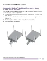
Orient the case by its length, and the length of the T-bar.
5
Rotate the case 45 degrees clockwise, or about 10 o’clock.
6
Push the back of the case onto the bottom of the T-bar.
7
Rotate the case 45 degrees counter-clockwise. The clips click as they fasten to the T-bar.
8
Verify that the unit has power by observing the LEDs.
CAUTION
If you are not using a 802.3af capable controller to power the Altitude 4522 Access Point,
ensure that only the Altitude 4522 Access Point’s designated power supply (PWRS-14000-148R) is
used. Using an incorrectly rated power supply could damage the unit and void the product warranty.
Do not actually connect to the power source until the cabling portion of the installation is complete.
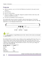
External Antenna Model Wall Mount
Instructions
A wall mount deployment requires hanging the Altitude 4522 Access Point along its width
or length using the pair of slots on the bottom of the unit. The Altitude 4522 Access Point
can be mounted on to any plaster, wood, or cement wall surface using the provided wall
anchors.
Wall Mount Hardware
●
Two customer provided wide-shoulder Phillips pan head self-tapping screws
(M3.5 x 0.6 x 20 mm)
●
Two wall anchors (customer supplied)
●
Security cable (optional)
NOTE
The following screws are recommended: (ANSI Standard) #6-18 X 0.875in. Type A or AB
Self-Tapping Screw, or (ANSI Standard Metric) M3.5 X 0.6 X 20mm Type D Self-Tapping Screw.
Summary of Contents for Altitude 4522 Series
Page 68: ......