


Integrated Antenna Model Wall Mount Instructions
Altitude™ 4522 Series Access Point Installation Guide
12
Signal loss can occur when metal, concrete, walls, or floors block transmission. Install the
Access Point in an open area or add Access Points as needed to improve coverage.
Antenna coverage is analogous to lighting. Users might find an area lit from far away to be
not bright enough. An area lit sharply might
minimize coverage and create
dark areas.
Uniform antenna placement in an area
(like even placement of a light bulb) provides even,
efficient coverage.
Place the Access Point using the following guidelines:
●
Install the Access Point at an ideal height of 10 feet from the ground.
●
Orient the Access Point antennas vertically for best reception (applies to external
antenna models only).
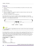
To maximize the Access Point’s radio coverage area, Extreme Networks recommends
conducting a site survey to define and document radio interference obstacles before
installing the Access Point.
Integrated Antenna Model Wall Mount
Instructions
Wall mounting requires hanging the Altitude 4522 Access Point along its width or length
using the two slots on the bottom of the unit. The Altitude 4522 Access Point can be
mounted on to any plaster, wood, or cement wall surface using customer supplied screw
hardware (M3.5 x 0.6 x 20 mm- or equivalent).
Wall Mount Hardware
●
Two wide-shoulder Phillips pan head self-tapping screws (customer supplied)
●
Two wall anchors (customer supplied)
●
Security cable (optional)
NOTE
The following screws are recommended: (ANSI Standard) #6-18 X 0.875in. Type A or AB
Self-Tapping Screw, or (ANSI Standard Metric) M3.5 X 0.6 X 20mm Type D Self-Tapping Screw.
Summary of Contents for Altitude 4522 Series
Page 68: ......