Extech Instruments MN42 User Manual Download Page 8

MN42-EU - V1.1 – 07/2010 

8

Maintenance 

WARNING

: To avoid electric shock, disconnect the test leads from any source of voltage 

before removing the back cover or the battery or fuse covers. 


WARNING: 

To avoid electric shock, do not operate your meter until the battery and fuse 

covers are in place and fastened securely. 

This MultiMeter is designed to provide years of dependable service, if the following care 
instructions are performed: 

1. 

KEEP THE METER DRY

. If it gets wet, wipe it off. 

2. 

USE AND STORE THE METER IN NORMAL TEMPERATURES.

 Temperature 

extremes can shorten the life of the electronic parts and distort or melt plastic parts. 

3. 

HANDLE THE METER GENTLY AND CAREFULLY.

 Dropping it can damage the 

electronic parts or the case. 

4. 

KEEP THE METER CLEAN.

 Wipe the case occasionally with a damp cloth. DO 

NOT use chemicals, cleaning solvents, or detergents. 

5. 

USE ONLY FRESH BATTERIES OF THE RECOMMENDED SIZE AND TYPE. 

Remove old or weak batteries so they do not leak and damage the unit. 

6. 

IF THE METER IS TO BE STORED FOR A LONG PERIOD OF TIME

, the battery 

should be removed to prevent damage to the unit. 

BATTERY INSTALLATION and LOW BATTERY INDICATION 

LOW BATTERY INDICATION 

The 

+

-

 icon will appear in the display when the battery voltage becomes low. Replace the 

batteries when this appears. 
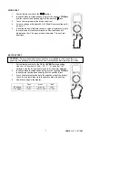
BATTERY REPLACEMENT 

1.  Disconnect the test leads from the meter. 
2.  Remove the Phillips head screws (2) which secure the rear battery compartment 

cover. 

3.  Remove the fuse/battery compartment cover to access the battery.  
4.  Replace the 9V battery, observing polarity. 
5.  Replace and secure the fuse/battery compartment cover . 

You, as the end user, are legally bound (

Battery ordinance

) to return all used 

batteries and accumulators; 

disposal in the household garbage is prohibited!


You can hand over your used batteries / accumulators at collection points in your 
community or wherever batteries / accumulators are sold! 

Disposal: 

Follow the valid legal stipulations in respect of the disposal of the 

device at the end of its lifecycle 

REPLACING THE FUSES 

1. 

Disconnect the test leads from the meter. 

2. 

Remove the Phillips head screws (2) which secure the rear battery compartment 
cover. 

3. 

Remove the fuse/battery compartment cover to access the fuses. 

4. 

Gently remove the fuse(s) and install new fuse(s) into the holder(s). 

5. 

Always use fuses of the proper size and value (0.2A/250V fast blow for the 200mA 
range, 10A/250V fast blow for the 10A range). 

6. 

Replace and secure the fuse/battery compartment cover . 

Summary of Contents for MN42

Page 1: ...User s Guide Digital Multimeter Model MN42 ...

Page 2: ...device is protected throughout by double insulation or reinforced insulation SAFETY INSTRUCTIONS This meter has been designed for safe use but must be operated with caution The rules listed below must be carefully followed for safe operation 1 NEVER apply voltage or current to the meter that exceeds the specified maximum Input Protection Limits Function Maximum Input V DC or V AC 600V AC and DC 20...

Page 3: ...y 3 Function switch 4 Positive jack 5 COM jack 6 10A jack Note Tilt stand fuse and battery compartment are on rear of unit Symbols Continuity Diode µ micro amps m milli volts amps k kilo ohms Ω Ohms Alternating AC current Direct DC current BAT Battery test Low battery icon 2 3 4 5 6 1 ...

Page 4: ...t the live parts inside some 240V outlets for appliances because the contacts are recessed deep in the outlets As a result the reading may show 0 volts when the outlet actually has voltage on it Make sure the probe tips are touching the metal contacts inside the outlet before assuming that no voltage is present CAUTION Do not measure AC voltages if a motor on the circuit is being switched ON or OF...

Page 5: ... DC CURRENT MEASUREMENTS CAUTION Do not make current measurements at 10 Amps for longer than 30 seconds Exceeding 30 seconds may cause damage to the meter and or the test leads 1 Insert the black test lead banana plug into the negative COM jack 2 For current measurements up to 200mA DC set the function switch to the highest mADC position and insert the red test lead banana plug into the mA jack 3 ...

Page 6: ...t so the rest of the circuit will not interfere with the resistance reading 4 Read the resistance in the display Move the function switch to the lowest Ω position that is greater than the anticipated resistance CONTINUITY CHECK WARNING To avoid electric shock never measure continuity on circuits that have a voltage potential 1 Set the function switch to the position 2 Insert the black lead banana ...

Page 7: ... TEST CAUTION Do not measure batteries while they are installed in the devices they are powering The batteries must be removed from installations before tests can be made 1 Set the function switch to the 1 5V or 9V BAT switch position Use the 1 5V position for AAA AA C D and other 1 5V batteries Use the 9V position for square 9V transistor batteries 2 Insert the black test lead banana plug into th...

Page 8: ...RY INDICATION LOW BATTERY INDICATION The icon will appear in the display when the battery voltage becomes low Replace the batteries when this appears BATTERY REPLACEMENT 1 Disconnect the test leads from the meter 2 Remove the Phillips head screws 2 which secure the rear battery compartment cover 3 Remove the fuse battery compartment cover to access the battery 4 Replace the 9V battery observing po...

Page 9: ...1 0 reading 2 digits 20mA 10µA 200mA 100µA 1 5 reading 2 digits 10A 10mA 2 0 reading 2 digits Resistance 200Ω 0 1Ω 0 8 reading 2 digits 2000Ω 1Ω 20kΩ 0 01kΩ 200kΩ 0 1kΩ 2000kΩ 1kΩ 1 0 reading 2 digits Battery Test 9V 10mV 1 0 reading 2 digits 1 5V 10mV Notes Accuracy specifications consist of two elements reading This is the accuracy of the measurement circuit digits This is the accuracy of the an...

Page 10: ...er is intended for indoor use and in accordance with Overvoltage Category III 600V Pollution Degree 2 PER IEC1010 OVERVOLTAGE INSTALLATION CATEGORY OVERVOLTAGE CATEGORY I Equipment of OVERVOLTAGE CATEGORY I is equipment for connection to circuits in which measures are taken to limit the transient overvoltages to an appropriate low level Note Examples include protected electronic circuits OVERVOLTA...

Reviews: