


MN42-EU - V1.1 – 07/2010
2
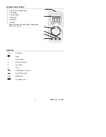
Introduction
Congratulations on your purchase of the Extech MN42 MultiMeter. The MN42 offers AC/DC
Voltage, DC Current, and Resistance testing. Proper use and care of this meter will provide
many years of reliable service.
Safety
This symbol adjacent to another symbol, terminal or operating device
indicates that the operator must refer to an explanation in the Operating
Instructions to avoid personal injury or damage to the meter.
This
WARNING
symbol indicates a potentially hazardous situation, which
if not avoided, could result in death or serious injury.
This
CAUTION
symbol indicates a potentially hazardous situation, which
if not avoided, may result damage to the product.
This symbol advises the user that the terminal(s) so marked must not be
connected to a circuit point at which the voltage with respect to earth
ground exceeds 600VAC or VDC.
This symbol adjacent to one or more terminals identifies them as being
associated with ranges that may, in normal use, be subjected to
particularly hazardous voltages. For maximum safety, the meter and its
test leads should not be handled when these terminals are energized.
This symbol indicates that a device is protected throughout by double
insulation or reinforced insulation.
SAFETY INSTRUCTIONS
This meter has been designed for safe use, but must be operated with caution. The rules
listed below must be carefully followed for safe operation.
1.
NEVER
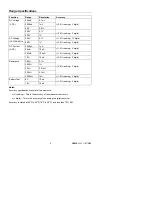
apply voltage or current to the meter that exceeds the specified maximum:
Input Protection Limits
Function Maximum
Input
V DC or V AC
600V AC and DC 200Vrms on the 200mV range
mA DC
200mA DC 250V fast acting fuse
ADC
10A 250V fast acting fuse
(30 seconds max every 15 minutes)
Resistance, Continuity
250Vrms 15 seconds max
2.
USE EXTREME CAUTION
when working with high voltages.
3.
DO NOT
measure voltage if the voltage on the "COM" input jack exceeds 500V above
earth ground.
4.
NEVER
connect the meter leads across a voltage source while the function switch is in
the current, resistance, or diode mode. Doing so can damage the meter.
5.
ALWAYS
discharge filter capacitors in power supplies and disconnect the power when
making resistance or diode tests.
6.
ALWAYS
turn off power and disconnect test leads before opening the covers to replace
the fuse or battery.
7.
NEVER
operate the meter unless the back cover and the battery and fuse covers are in
place and fastened securely.
8.
If the equipment is used in a manner not specified by the manufacturer, the protection
provided by the equipment may be impaired.
WARNING
CAUTION
MAX
600V


