background image

8-line  Digital  I/O  to  Ethernet  Adapter


3 


DC  Jack  Power  Connector:

  A  5V/2A  AC  adapter  is  supplied  with 

this product. 


RJ45  Ethernet  Connector:

  10/100Mbps  Ethernet  port.  It  supports 

auto cross-over feature. You can use the same cable to connect 
to either a Hub/Switch or a host computer. 
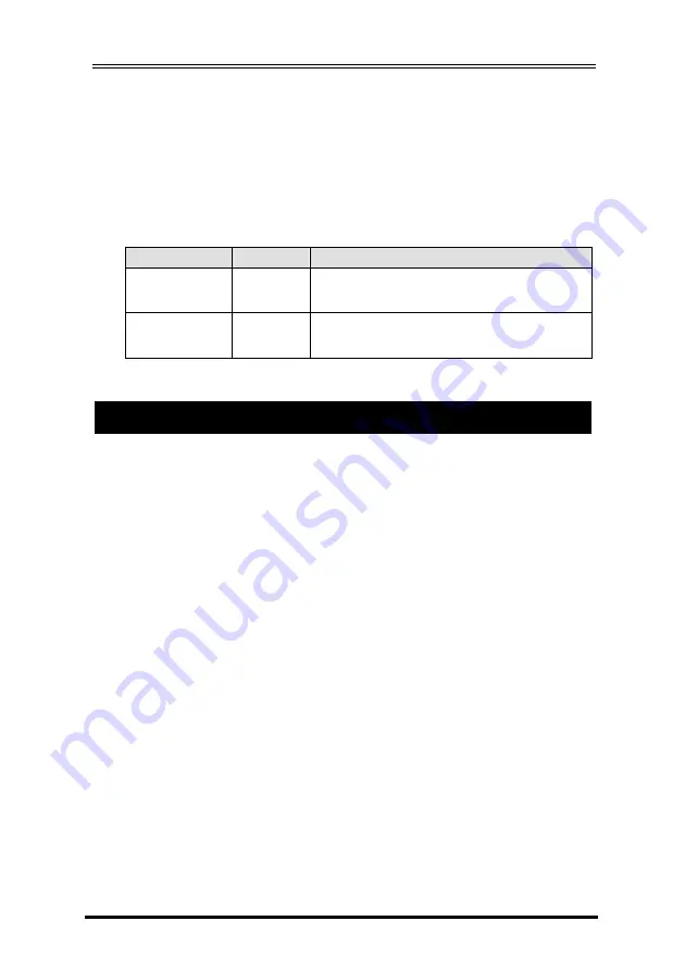
 

LED  Indicators: 

There  are  2  LAN  LEDs  on  the  rear  panel.  They  are 

described as the following table: 


LED Name 

Color 

LED Function 

Link/Activity 


Green 

Steady on:

 Linked. 

Blinking:

 Transferring data 

10/100Mbps 


Amber 

Steady on:

 Linked in 100Mbps mode. 

Off:

 Linked in 10Mbps mode. 


1.


Use static electricity discharge precautions. 

Remove possible static discharge potential from any objects that 
the 

Adapter

  may  come  in  contact  with  before  installation.  This 

can be accomplished by touching a bare metal chassis rail after 
you have turned off the power.   

2.


Attached  the  power  adapter.  +5V  DC  power  needs  to  be 
connected to  either  the  DC  jack  or  the  Terminal  Blocks,  but  not 
simultaneously.  Once  the  power  is  connected  to  the  DC  jack, 
the  +5V  power  will  output  to  the  10-pin  Terminal  Blocks 
immediately.  So  it  is  not  allowed  to  connect  any  power  to  the 
Terminal  Blocks  if  the  DC  jack  is  connected  to  a  5V  AC  power 
adapter. 

3.


Connecting LAN cable: 

Use a standard straight-through Ethernet 

cable  to  connect  to  a  Hub  or  Switch.  If  you  connect  the 

Adapter

  to  your  computer’s  Ethernet  port  instead,  you  don’t 

need  to  change  to  a  cross-over  type  cable  since  the 

Adapter


provides auto cross-over feature. 

4.


Connect the Adapter’s DI and DO pins to your devices. 

5.


Use  the  Wall  or  DIN  RAIL  mounting  Kit  (optional)  if  you  want  to 
place the product on the industrial DIN RAIL.   

3. Hardware Installation 

Summary of Contents for EX-6011

Page 1: ...emote lighting and power control etc Features 4 Digital Input and 4 Output Lines over a 10 pin Terminal Blocks 2 Non inverted and 2 Inverted Output Lines Provides ESD and Surge Protection for all I O...

Page 2: ...5V OUTPUT If the DC Jack is unconnected it can be powered by this pin with 5V input power Switch to Restore Default Settings This switch can be used to reset the product to its factory default setting...

Page 3: ...is can be accomplished by touching a bare metal chassis rail after you have turned off the power 2 Attached the power adapter 5V DC power needs to be connected to either the DC jack or the Terminal Bl...

Page 4: ...refer to the following sections After that the Adapter will send a DHCP request to the DHCP server which will assign a dynamic IP address net mask and gateway to the Adapter the first time it is conne...

Page 5: ...ress using Web Browser Please make sure your PC s IP address is set at the same subnet of the Adapter If not you usually need to change your PC s IP address from Local Area Connection Properties here...

Page 6: ...sword Then go to change your IP address as well other parameters if required 3 Setting the IP address using Em exe Utility The Em exe is a Microsoft Windows based utility to find all the Adapters conn...

Page 7: ...disable your firewall or the anti virus software then try again 4 The Adapter Settings When you entered Setup Menu of the Adapter the following page will be available for your access Please click Upda...

Page 8: ...ned by the DCHP server if DHCP client is enabled DHCP client If disable then IP address Subnet mask and Gateway address must be assigned manually Socket port of HTTP setup Port number for HTTP Setup M...

Page 9: ...s Device ID User assigned device ID number acceptable range is 0 to 65535 Device Name 16 characters maximum to describe the application facility Device Model 16 characters maximum to indicate the appl...

Page 10: ...ine Digital I O to Ethernet Adapter 10 1 Launch the HyperTerm utility it will create a new connection please type the connection name type a in this case 2 Enter the Adapter s IP address and port numb...

Page 11: ...rn and a line feed indicating the current state of all 8 DIO lines 11111111 for example The string is formatted as the following table 1 1 1 1 1 1 1 1 4 In HyperTerm click File Properties Settings ASC...

Page 12: ...re are four legal values 01 02 03 and 04 m 0 or 1 0 means to drive the I O pin to LOW state 1 means to set the I O pin to HIGH state Stands for 2 characters a Carriage return and a Line feed 0x0D and...

Page 13: ...to the following screen shot it was actually tested with a short wire to ground the DI_0 DI_1 DI_2 then DI_3 pins sequentially You will see it detected 0 when grounded then 1 when released sequential...

Page 14: ...anywhere in the world via Internet or LAN as if it is attached directly to the remote PC When the attached serial port device or digital I O Adapter sends communication data it is actually transmitte...

Page 15: ...Adapter 15 2 While installing the driver please enter the password 3 Follow the on screen instructions to complete the Installation you are ready to launch the software utility to enter the hardware...

Page 16: ...at CentosSEC should be run as an administrator for some Windows such as 2008 Vista and 7 their UAC User Account Control will limit the CentosSEC from working properly if you have only standard user pr...

Page 17: ...following screen will appear click the Help button will list the supported operations and details You may need to click Add to create a new COM port then click Update All to save the settings You don...

Page 18: ...Net Protocol to RAW instead of TELNET for this digital I O Adapter After clicked Update All button the status field should become Available If it is Registered it won t work properly You need to revi...

Page 19: ...e digital IO lines remotely without any extra software or drivers TCP Server mode The TCP Server mode provides the service at the TCP IP socket port The default setting of this Adapter is set at 192 1...

Page 20: ...2 168 1 254 port 100 the Slave unit should set its Destination IP to match the Master s service port 192 168 1 254 port 100 In this mode the IO pins are remotely connected without any software support...

Page 21: ...r Slave Configuration The Slave unit settings included its IP address 192 168 1 252 must be different from the Master unit mode IO Extender Slave and Destination IP port Master unit s IP port 192 168...

Page 22: ...mption Mechanical Specifications Material Gross Weight Environmental Operating Temperature Storage Temperature 10 100Mbps Ethernet RJ45 10 100Mbps 4 TTL CMOS Input Lines DI_0 to DI_3 4 TTL CMOS Output...

Page 23: ...ne Digital I O to Ethernet Adapter 23 Operating Humidity 5 to 95 RH Electrical Characteristics Parameters Values Input DI_0 DI_1 DI_2 DI_3 Low High 0 8V 2 0V Output DO_0 DO_1 DO_2 DO_3 Low High 0 55V...

Page 24: ...8 line Digital I O to Ethernet Adapter 24...

Reviews: