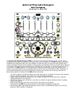


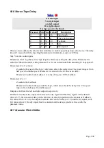

X is clock input
Y is wavetable input
Z is trigger
A & B are wavetable output
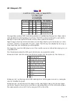
Parameter Min Max Default
Description
0
0
99
0
Chooses the wavetable.
1
-32 32
0
Y Offset.
2
-32 32
32
Output A attenuverter.
3
-32 32
-32
Output B attenuverter.
4
-15 8
0
Envelope time multiplier.
5
0
2
0
Trigger mode.
This algorithm is essentially a version of the Clockable Wavetable LFO, but with a trigger input
instead of being free-running. As such it can be thought of as a kind of envelope generator, where
the envelope shape is defined by an audio file in the wavetable.
See 'Loading wavetables' above for a description of how to load wavetables onto the SD card.
Input X is the clock input. Any clock pulse in excess of 1V can be used. The time between rising
trigger edges is used to set the envelope time.
The Y input controls the lookup point in the wavetable, with a range of ±5V covering the whole
table. Parameter 1 offsets the Y CV, effectively providing a means of manual wave selection.
The Z input is the trigger for the envelope to start.
Outputs A & B are the result of the wavetable lookup. Each output has its own attenuverter on
parameters 2 & 3 respectively.
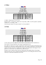
Parameter 4 applies a multiplier to the envelope time, according to the table in the Clockable
Delay/Echo section, above.
Parameter 5 sets the triggering mode, according to the following table.
Parameter 5 value
Triggering mode
0
Envelope triggered by every pulse on Z.
1
Envelope cannot be retriggered during a cycle.
2
Gated – envelope ends when Z goes low.
K-5 Programmable Quantizer
Page 94