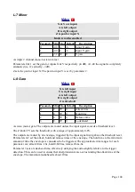


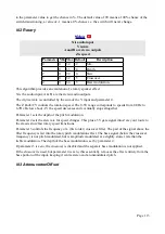


A = X * scale + offset
B = Y * scale + offset
Z is not used
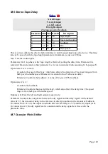
Parameter Min Max Default
Description
0
-100 100 50
Attenuversion A.
1
-100 100 0
Offset A.
2
-100 100 50
Attenuversion B.
3
-100 100 0
Offset B.
This algorithm provides two independent channels of attenuversion (that is, attenuation and possible
inversion) and offset.
Parameters 0 & 2 are the attenuversion parameters, scaled such that a parameter value of 50 gives
100% i.e. the signal level is unchanged.
Parameters 1 & 3 are the offset parameters, scaled such that a parameter value of 100 gives 10V.
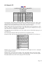
N-4 Low Pass Gate
X and Y are stereo inputs
A and B are stereo outputs
Z is frequency/'strike'
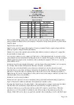
Parameter Min Max Default
Description
0
0
31
0
Resonance.
1
1
99
50
Up slew.
2
1
99
50
Down slew.
This algorithm is a stereo low pass gate, that is, a combination of low pass filter and VCA. It makes
no claim to emulate any particular bit of hardware, classic or modern, but the response of the filter
to a 'strike' on the frequency input has been designed to be somewhat like that of a vactrol-based
low pass gate.
X & Y are the audio inputs; A & B are the audio outputs.
Z controls the filter frequency/VCA CV. This has slew applied to it, which is controlled by
parameters 1 & 2.
Parameter 0 sets the filter resonance.
N-5 Pulsar VCO
Page 114