background image

Troubleshooting

The DC Shunt MUST be installed on the NEGATIVE (-) terminal of the battery, (Figure 11) to avoid
blowing the fuse in the meter when testing the output of the 16 amp system. All connections must be clean
and tight for correct readings.

1.

Connect stator wire harness to regulator-rectifier.

2.

Install DC Shunt (4) on NEGATIVE battery terminal.

3.

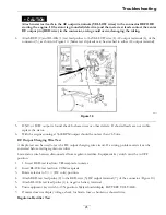
Insert RED test lead into VΩ receptacle in meter and connect to RED post terminal on shunt (5), Figure 11.

g268088

Figure 11

4.

Insert BLACK test lead in COM receptacle in meter. Connect to BLACK post terminal on shunt (3).

5.

Rotate selector to 300 mV position.

6.

With the engine running at 3600 RPM, the output should be 3-20 Amps.

Note:

Depending on battery voltage and/or current draw on system

If NO or LOW output is found, be sure that regulator-rectifier is grounded properly and all equipment
connections are clean and secure. If there is still NO or LOW output, replace the regulator-rectifier.

26


Summary of Contents for Z-Plug

Page 1: ...Z PLUG For Serial Nos 404 314 159 and Higher Part No 4504 453 Rev B ...

Page 2: ...s and limitations outlined in this manual Operating the Z Plug outside of the stated safety guidelines presented in this manual run the risk of injury and a void in the warranty Product Registration Immediately record the model and serial number of your Z Plug in the spaces below These numbers can be found on the left side of the engine plate Providing this information will help assure that you ge...

Page 3: ...ation 15 Spreader Operations 15 Spreader System 16 Aerator Operations 16 Maintenance 19 Periodic Maintenance 19 Engine Maintenance 19 Hydraulic System Maintenance 20 Traction Unit Maintenance 20 Spreader Maintenance 20 Aerator Head Tine Maintenance 20 Troubleshooting 23 Engine 23 Hydraulics 23 Tracking 23 Granular 23 Charging Issues 24 Schematics 27 3 ...

Page 4: ...y be hazardous and toxic to you bystanders animals plants soils or other property Carefully read and follow the chemical warning labels and Safety Data Sheets SDS for all chemicals used and protect yourself according to the chemical manufacturer s recommendations Ensure that as little skin as possible is exposed while using chemicals Use appropriate Personal Protective Equipment PPE to guard again...

Page 5: ...sories and attachments Wear appropriate clothing including safety glasses substantial slip resistant footwear and hearing protection Tie back long hair and avoid loose clothing or loose jewelry which may get tangled in moving parts CAUTION This machine produces sound levels in excess of 85 dBA at the operator s ear and can cause hearing loss through extended periods of exposure Wear hearing protec...

Page 6: ... clean the machine when people especially children or pets are in the area Make sure the operator platform is clean and free from chemical residue and debris buildup Operation WARNING Operating engine parts especially the muffler become extremely hot Severe burns can occur on contact and debris such as leaves grass brush etc can catch fire Allow engine parts especially the muffler to cool before t...

Page 7: ...ning going up or down hills suddenly changing speeds or while driving over rough surfaces Shifting loads can cause the unit to tip over When operating with a heavy load reduce your speed and allow for sufficient stopping distance Use extra caution on slopes Reduce speed and load when operating on rough terrain uneven ground and near curbs holes and other sudden changes in terrain Loads may shift c...

Page 8: ...spreader gate set the parking brake stop engine and remove key or disconnect spark plug wire Wait for all movement to stop before adjusting cleaning or repairing Keep engine and engine area free from excessive grease or oil and other debris which can accumulate in these areas These materials can become combustible and may result in a fire Let engine cool before storing and do not store near flame ...

Page 9: ...pment parts and or accessories may alter the warranty controllability and safety of the machine Unauthorized modifications to the original equipment or failure to use original manufacturer parts could lead to serious injury or death Unauthorized changes to the machine engine fuel or venting system may violate applicable safety standards such as ANSI OSHA and NFPA and or government regulations such...

Page 10: ...ckward tip over Backward tip over could cause serious injury or death Use extreme caution when operating a machine on a ramp Use only a single full width ramp Do Not use individual ramps for each side of the machine If individual ramps must be used use enough ramps to create an unbroken ramp surface wider than the machine Avoid sudden acceleration while driving machine up a ramp to avoid tipping b...

Page 11: ...es to shield eyes and rubber gloves to protect skin and clothing when handling electrolyte Do Not swallow electrolyte In the event of an accident flush with water and call a doctor immediately Federal law states that batteries should not be placed in the garbage Management and disposal practices must be within relevant federal state or local laws If a battery is being replaced or if the unit conta...

Page 12: ...to expose the adhesive surface Apply only to a clean dry surface Smooth to remove any air bubbles Familiarize yourself with the following safety signs and instruction labels They are critical to the safe operation of your machine decal126 2055 126 2055 1 Wheel lug nut torque to 129 N m 95 ft lb 2 Wheel hub nut torque to 319 N m 235 ft lb 3 Read the Operator s Manual before performing maintenance c...

Page 13: ...arking brake and shut off the engine before leaving the machine 22 Continuous variable setting 8 Crushing dismemberment hazard of bystanders forward and reverse do not carry passengers look behind and down when reversing 23 Throttle slow 9 Thrown object hazard keep bystanders away 24 Hour meter 10 Warning only operate across slopes do not operate up and down slopes 25 Engine off 11 Caustic liquid ...

Page 14: ...Safety decal135 6281c 135 6281 14 ...

Page 15: ...back on the Joy Sticks If a turn is desired push opposite Joy Stick of the direction you want the unit to head forward if wanting to turn left push the right Joy Stick forward while keeping the left Joy Stick slightly back of the right thus allowing the right tire to turn more than the left Push more on the left Joy Stick if you desire to turn the unit to the right Be cautious as turn radius chang...

Page 16: ...o the right placing product to the middle of the impeller Your machine is equipped with a 120 lb Spyker model spreader The hydraulic spreader motor with the spreader motor control has the ability to vary spread widths from 3 to 25 feet This depends on volume density particle size and rate of travel and weather conditions The pattern can be increased or decreased while spreading depending on needs ...

Page 17: ...ty The Locking Caster System is applied when the operator compresses the Locking Caster System foot pedal located on the right side of the foot plate When compressing the foot pedal locking mechanism slides over the caster pin locking the wheel in the forward straight position This system is spring loaded so by releasing this pedal it will release the lock on the front caster wheels Aerator Tine H...

Page 18: ...removable weights are heavy Use care when lifting them Make sure that you can hold them securely before lifting them Use caution when positioning your hands so that you Do Not set them on your hands fingers or feet It is recommended to use two people when removing weights 18 ...

Page 19: ...ent oil are acceptable if classified for service SF SG SH SJ or higher Do not use special additives Change engine oil after first 5 hours and then every 50 hours thereafter If the oil level is below the ADD mark add oil until it reaches the FULL mark Start the engine and run for a few seconds Turn engine off and check dipstick for proper fill level g286804 Figure 8 1 Engine oil drain hose behind e...

Page 20: ... bolts washers nuts pins and other mounting hardware of Z Plug once a week to ensure that hardware pieces are properly tightened Spreader Maintenance The Z Plug comes equipped with a 120 lb spreader and requires the same amount of attention and maintenance USE COMPRESSED AIR NOT WATER WHEN CLEANING HOPPER Lubricate Silicone Spray Hopper Deflector and Diffuser cables weekly Clean debris and product...

Page 21: ...e X Belt Tension 1 2 inch deflection at 15lbs X Belt Wear cracks tears or missing material X Hopper Cables lubricate w Silicone Spray X Accuway Cable lubricate w Silicone Spray X Deflector Shield Cable if applicable lubricate w Silicone Spray X Bottom of Hopper Tub wire brush cleaning X Hopper Bottom Bushing change if needed X Replace Impeller change if needed X Engine Oil check X 21 ...

Page 22: ...heck change if needed 25 hrs Engine Spark Plugs X Replace Hydraulic Oil and filter change After first 100 hrs and every 500 hrs thereafter Hydraulic Oil Level check X Hydro System Fittings check for leaks X In Line Filter check X In Line Filter Gasket check X Pillow Block Bearings X Aerator Tine Inspection X Aerator Tine Hardware Nut and Bolt X Ball Swivel Inspection X Blow off debris daily X 22 ...

Page 23: ...ps There are Tow Valves on each of the hydro pumps hex head with hole running through it on the left side rear of the hydraulic pump that needs to be turn at least 1 revolutions counterclockwise to open the hydraulic system but NEVER remove Once the unit is brought to a desired location remember to tighten the tow valves back tight clockwise Tracking Unit not tracking straight when pushing both co...

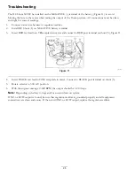
Page 24: ...utput leads to the regulator rectifier The regulator rectifier converts the AC current to DC and regulates current to the battery The charging rate will vary with engine RPM and temperature 1 BLACK test lead from meter 1 Figure 9 2 RED test lead from meter 2 3 Connector 3 4 Two YELLOW AC input leads 4 5 RED DC OUTPUT WIRE 5 6 AC Output terminals 6 7 RED DC output lead 7 to connector Note Stator re...

Page 25: ...ine running at 3600 RPM output should be no less than 26 Volts DC Output Charging Wire Test A simple test can be used to test the DC output charging wire circuit If a wiring problem exists it can be corrected before testing regulator rectifier Leave stator wire harness disconnected from regulator rectifier Equipment key switch must be in OFF position 1 1 Insert RED test lead into VΩ receptacle in ...

Page 26: ... into VΩ receptacle in meter and connect to RED post terminal on shunt 5 Figure 11 g268088 Figure 11 4 Insert BLACK test lead in COM receptacle in meter Connect to BLACK post terminal on shunt 3 5 Rotate selector to 300 mV position 6 With the engine running at 3600 RPM the output should be 3 20 Amps Note Depending on battery voltage and or current draw on system If NO or LOW output is found be sur...

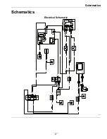
Page 27: ...SE LOWER J1626 J1628 RIGHT THUMB SWITCH LEFT THUMB SWITCH BLACK BLACK ORANGE ORANGE ORANGE BLACK J1627 RED SP1608 SP1609 ATC ATO FUSE HOLDER MAIN F27 20A SPEEDOMETER 12VDC GND SENSOR SENSOR P1609 SP1607 P1611 RED BLACK RED BLACK YELLOW YELLOW SPEED SENSOR CABLE FRAME GROUND FRAME GROUND FRAME GROUND J1622 ATC ATO FUSE HOLDER SPEEDOMETER WHITE J1616 J1617 J1613 J1614 K1601 START SOLENOID RED RED RE...

Page 28: ...r Fill in Below Date Purchased Engine Model No and Spec No Model No Engine Serial No E No Serial No 2019 Exmark Mfg Co Inc 2101 Ashland Ave Beatrice NE 68310 All Rights Reserved Part No 4504 453 Rev B 402 223 6375 Fax 402 223 5489 Printed in the USA 4504 453 B www exmark com ...

Reviews: