Maintenance
control arms to prevent the drive system from
stalling.
2.
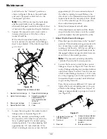
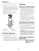
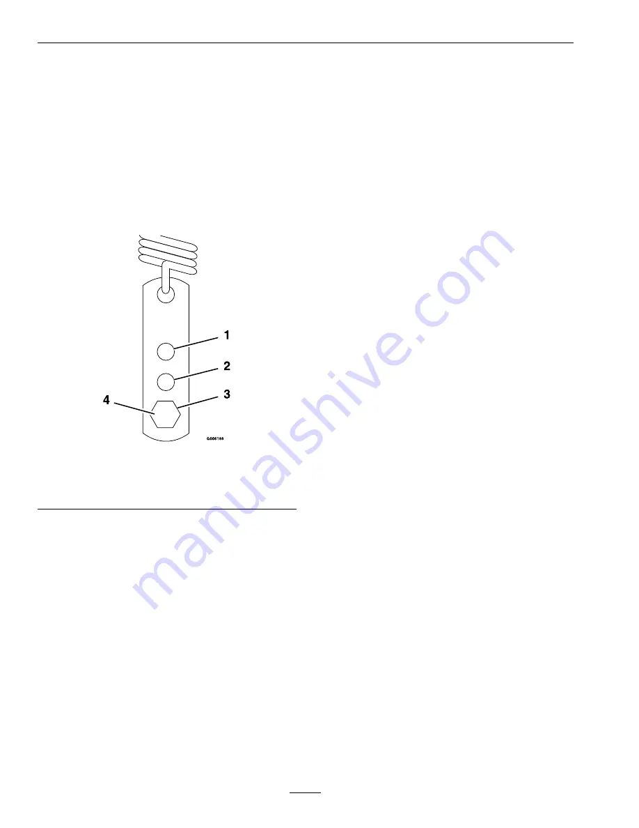
For a heavier drive setting, relocate the spring
anchor links to either the “medium” or “heavy
duty” positions as shown in Figure 23. The spring
anchor links are attached to the upper rear corner
of the hydro drive shields on the left and right
hand sides of the machine.
Note:
In the “medium” or “heavy duty”
positions, the drive lever forces at the upper
handle will also be increased.
g006188
Figure 23
1.
Heavy duty
3.
Standard
2.
Medium duty
4.
Retaining bolt
Park Brake Adjustment
1.
Stop engine and wait for all moving parts to stop.
2.
Disengage the park brake.
3.
Remove the hairpin in the lower park brake
linkage. Turn the linkage in the yoke until there is
3/16 inch (.48 cm) to 1/4 inch (.64 cm) clearance
between the park brake tire bars and the tires with
the park brake disengaged. Re-install the hairpin.
Cleaning
Cleaning and Storing Safety
•
Park machine on level ground, disengage drives,
set parking brake, stop engine, remove key,
and disconnect spark plug wire. Wait for all
moving parts to stop before leaving the operator’s
position. Allow the machine to cool before
servicing, adjusting, fueling, cleaning, or storing.
•
Clean grass and debris from the cutting unit,
muffler, drives, grass catcher, and engine
compartment to prevent fires.
•
Allow the machine to cool before storing the
machine in any enclosure. Do not store the
machine or fuel container, or refuel, where there
is an open flame, spark, or pilot light such as on a
water heater or other appliance.
Clean Debris From Machine
Service Interval: Before each use or daily
1.
Stop engine, wait for all moving parts to stop, and
remove key. Engage parking brake.
2.
Clean off any oil, debris, or grass build-up on the
machine and cutting deck, especially under deck
belt shields, around the fuel tank, around engine
and exhaust area.
Important:
You can wash the machine with
mild detergent and water. Do not pressure
wash the machine. Avoid excessive use of
water, especially near the control panel,
around the engine, hydraulic pumps, and
motors.
Clean Engine and Exhaust
System Area
Service Interval: Before each use or daily
(May be required more
often in dry or dirty
conditions.)
40
Summary of Contents for VIKING 346
Page 1: ...VIKING For Serial Nos 408 644 346 Higher Part No 4505 182 Rev A ...
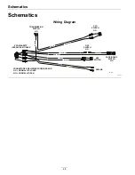
Page 45: ...Schematics g010189 45 ...
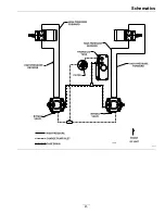
Page 47: ...47 ...

