


Maintenance
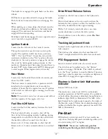
A. Install bushing through blade with bushing
flange on bottom (grass) side of blade.
Figure 11
1.
Install bushing in blade prior to installing bushing in
spindle.
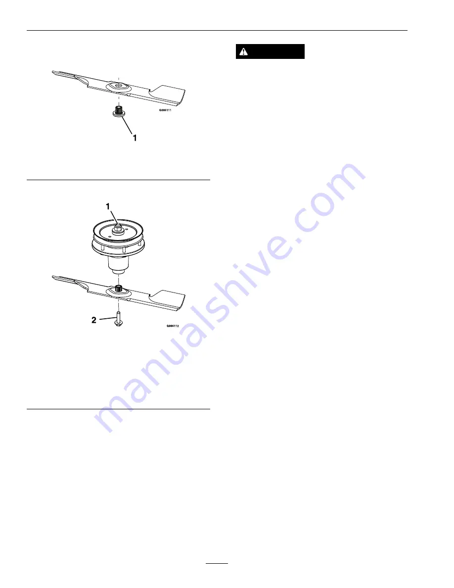
B. Install bushing/blade combo into spindle.
Figure 12
1.
Use wrench here for
blade installation. This
nut has been torqued to
90–110 ft-lb (122–149
N-m)
2.
Torque to 55-60 ft-lb
(75-81 N-m) Apply
lubricant to threads
as needed to prevent
seizing. Copper-based
anti-seize preferable.
Grease acceptable
substitute.
C. Apply lubricant to threads of blade bolt as
needed to prevent seizing. Copper-based
anti-seize preferable. Grease acceptable
substitute. Install blade bolt finger tight. Place
wrench on the top spindle nut then torque the
blade bolts to 55-60 ft-lb (75-81 N-m).
WARNING
Incorrect installation of the blade or
components used to retain the blade can
be dangerous. Failure to use all original
components and assembled as shown could
allow a blade or blade component to be
thrown out from under the deck resulting in
serious personal injury or death.
Always install the original Exmark blades,
blade bushings, and blade bolts as shown.
Check Safety Interlock
System
Service Interval: Before each use or daily
1. Check starting circuit. Starter should crank with:
Operator Presence Control levers
depressed
,
speed control lever in
neutral
, and PTO
disengaged
.
Try to start the engine with OPC levers
disengaged
, speed control lever in
neutral
and
PTO
disengaged-starter must not crank.
Try to start with, OPC levers
depressed
, speed
control lever in any speed but
neutral
and PTO
disengaged-starter must not crank.
Try to start with OPC levers
depressed
,
speed control lever in
neutral
and PTO
engaged-starter must not crank.
.
2. Check OPC circuits. Clear the area. Run engine
at one-third throttle, then, with drive levers and
neutral lock latches in
neutral lock position
,
move the speed control lever out of neutral and
release OPC levers
engine must stop.
Again,
run engine at one-third throttle, move the speed
control lever to
neutral
, engage PTO and release
OPC levers-
engine must stop.
Note:
Park brake must be disengaged before the
speed control lever is moved out of neutral or engine
will kill.
Note:
If machine does not pass any of these tests,
do not operate. Contact your authorized
EXMARK
SERVICE DEALER.
Important:
It is essential that operator safety
mechanisms be connected and in proper
operating condition prior to use for mowing.
26
Summary of Contents for TURF TRACER X-SERIES
Page 1: ...TURF TRACER X SERIES For Serial Nos 920 000 Higher Part No 4500 699 Rev A ...
Page 11: ...Safety 103 2242 103 2243 103 4935 103 2432 116 0404 11 ...
Page 12: ...Safety 116 4296 EFI Units Only 1 Fast 2 Slow 117 2718 12 ...
Page 38: ...Schematics Schematics Electrical Diagram All units except Kohler EFI 38 ...
Page 39: ...Schematics Electrical Diagram Kohler EFI 39 ...
Page 40: ...Schematics Electrical Logic Schematic All units except Kohler EFI 40 ...
Page 41: ...Schematics Electrical Logic Schematic Kohler EFI 41 ...
Page 42: ...Schematics Hydraulic Diagram 42 ...
Page 44: ...Notes 44 ...
Page 45: ...Service Record Date Description of Work Done Service Done By 45 ...
Page 46: ...46 ...


