- 18 -
4. OPERATION INSTRUCTIONS
4.1 Controls
4.1.1
Operator Presence Control (OPC) Levers: Located on the upper handle assembly
directly above the handle grips.
When these levers are depressed, the OPC
system senses that the operator is in the normal operator's position.
When
the levers are released, the OPC system senses that the operator has moved
from the normal operating position
and will kill the engine if either the speed
control lever is
not in the neutral
position or the
blade clutch is engaged
.
4.1.2
Speed Control Lever: Located in middle of control console, it controls the maximum
forward speed and is infinitely variable from neutral (0 mph) to 6.2 mph.
4.1.3
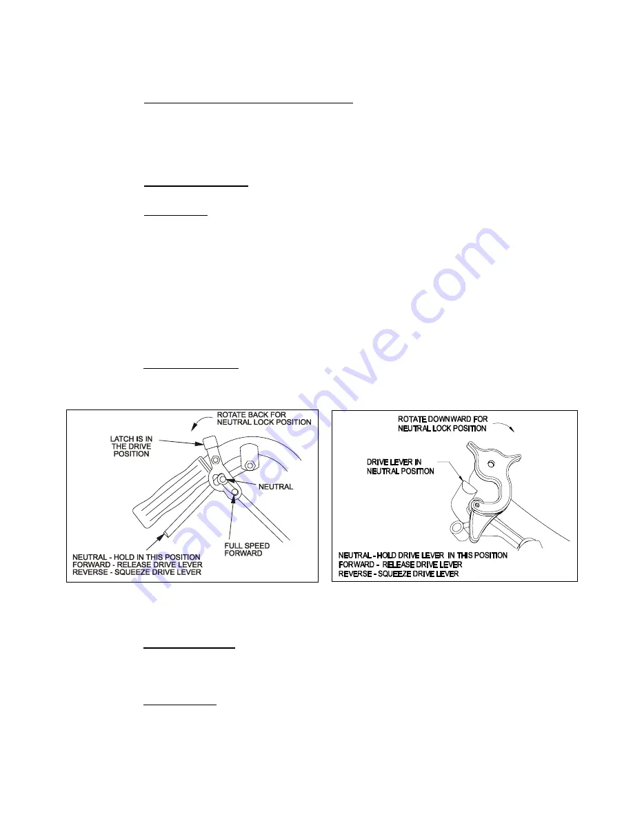
Drive Levers: Located on each side of the upper handle assembly directly below
the handle grips (See Figure 7). These levers individually control the speed and
direction of each drive wheel. When the speed control lever is moved out of the
neutral position and the neutral lock latches are moved into the drive position, as
shown in Figure 7, and the drive levers are released, the drive wheels are engaged
in the forward direction.
Squeezing the left hand and/or right hand lever causes the left hand and/or right
hand drive wheel respectively to slow down, stop, or reverse, depending on how far
each drive lever is "squeezed". Squeezing the drive levers beyond the neutral
position causes the drive wheels to engage in the reverse direction regardless of the
position of the neutral lock latches and the speed control lever.
4.1.4
Neutral Lock Latch: Located directly above the drive levers. These latches allow the
operator to lock the drive levers in a "neutral" position where neither of the drive
wheels are engaged in either a forward or reverse direction (See Figure 7).
STANDARD PISTOL GRIP HANDLES
ECS HANDLES
FIGURE 7
DRIVE LEVER, NEUTRAL LOCK LATCH OPERATION
4.1.5
PTO Engagement: Located on the left side of the upper handle. To engage the
blades, push the lever forward, or away from the operator, until the linkage locks
over-center. To disengage the blades, pull the lever to the rear, or towards the
operator.
4.1.6
Choke Control: Choke is used to aid in starting a cold engine.
The choke control is located on the front left corner of the fuel tank support and is
activated by pulling the control outward.
Once the engine has started move the choke control to the off position and move
the throttle to the medium or full throttle position.
Summary of Contents for Turf Tracer HP TT3615KA
Page 1: ......
Page 45: ... 40 8 WIRING DIAGRAMS ...
Page 46: ... 41 9 HYDRAULIC DIAGRAM ...
Page 49: ... 44 NOTES ...
Page 50: ... 45 SERVICE RECORD Date Description of Work Done Service Done By ...


