


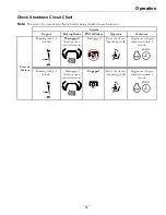

Operation
the machine to prevent someone from accidentally
starting the engine.
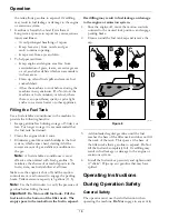
Blade Control Switch (Power
Take-Off)
Located on control panel.
The blade control switch, represented by a power
take-off (PTO) symbol, engages and disengages
power to the mower blades (see Figure 4).
Pull up on the blade control switch to “ON” to
engage the blades.
Push down on the blade control switch to “OFF”
to disengage the blades.
Throttle Lever
Located on control panel.
The throttle is used to control engine speed. Moving
throttle lever forward will increase engine speed and
moving throttle lever to the rear will decrease engine
speed. Moving the throttle forward until it stops is
full throttle.
Choke Control
The choke is used to aid in starting a cold engine. Do
Not run a warm engine with the choke in the “ON”
position. Moving the choke lever forward will put the
choke in the “ON” position and moving the choke
lever to the rear will put the choke in the “OFF”
position.
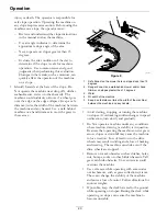
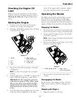
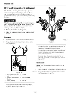
Motion Control Levers and Parking
Brake Position
The motion control levers located on each side of
the seat (Figure 5).
The motion control levers are speed sensitive controls
of independent wheel motors. Moving a lever
forward or backward turns the wheel on the same side
forward or in reverse; wheel speed is proportional to
the amount the lever is moved.
Moving the control levers outward from the center
T-slot position engages the parking brake on the drive
wheels. Always position the motion control levers
into the parking brake position when you stop the
machine or leave it unattended. The machine must be
tied down and brake engaged when transporting.
g333788
Figure 5
1.
Parking brake (handles
out)
4.
Forward
2.
Neutral operate position
(handles in)
5.
Neutral (operate)
3.
Front of machine
6.
Reverse
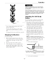
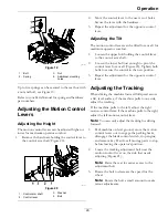
Deck Height Adjustment Hand
Lever—For 34 and 42 Inch Models
Note:
50 inch models have both deck height
adjustments: hand lever and foot assist pedal.
Located below the RH motion control lever.
Pull the lever inward and rearward to raise the cutting
deck. Allow the handle to move forward to lower the
cutting deck. Move the deck height adjustment lever
outward at the desired height of cut. Only adjust the
height of cut while the machine is not moving.
15
Summary of Contents for QUEST 346
Page 1: ...QUEST For Serial Nos 408 644 346 Higher Part No 4505 333 Rev A ...
Page 65: ...Schematics Schematics Electrical Logic Schematic g330623 65 ...
Page 67: ...Notes 67 ...
Page 68: ...Notes 68 ...
Page 69: ...Service Record Date Description of Work Done Service Done By 69 ...
Page 70: ...70 ...


