Operation
Operation
Note:
Determine the left and right sides of the
machine from the normal operating position.
Important:
Due to the added weight of the
Bagger, it is important to ensure the parking
brake on your mower is adjusted properly. Before
installing the Bagger, make sure to re-adjust the
parking brake on your mower as outlined in the
“Adjusting the Parking Brake” procedure in the
Maintenance section of the tractor Operator's
manual.
Pre-Start
Make sure you understand the controls, their
locations, their functions, and their safety
requirements.
Ensure the belt cover, bags, tubes and hopper are in
good condition, properly attached, and latched.
Important:
Verify that the hopper mount
brackets are installed on your unit prior to
operation.
Refer to the Maintenance section and perform all the
necessary inspection and maintenance steps.
Operating Instructions
Mowing
1. To remove the bags, first disengage the PTO, stop
the engine and wait for all moving parts to stop.
Open the hopper and remove the bags by lifting
up on the rear of the bag, then unhooking the
front clip. Empty the bags by inverting them.
2. Reinstall bags and close the hopper before
continuing mowing.
Tips for mowing conditions:
•
Maintaining a ground speed that does not pull
down the engine RPM will allow for the highest
productivity and best quality of cut. Bogging the
engine RPM down by going too fast will cause
plugging and quality of cut issues.
•
When the Bagger gets full, there will be slight
blowout from the front right corner of the deck.
Emptying the Bagger at this point will minimize
the potential for the tube to plug.
Bagger Removal for Side Discharge
1. Stop engine, remove key, and wait for all moving
parts to stop. Engage parking brake.
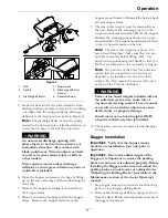
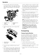
2. Release the latches on the lower tube assembly.
Remove the upper tube from the lower tube
assembly and the hopper.
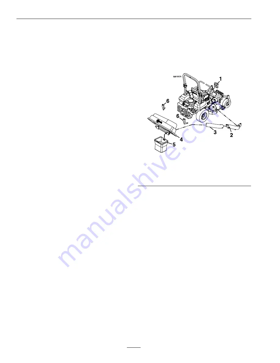
Figure 5
1.
Toe board weight
4.
Hopper
2.
Lower tube assembly
5.
Bag
3.
Upper tube
6.
Hopper mount brackets
3. Rotate the lower tube assembly latch upward to
unlock the it from the deck. Slightly rotate the
lower assembly outward and remove it from the
deck.
4. To install the discharge deflector, orient the spring
so that the short leg point towards the discharge
deflector and the longer leg points towards the
deck as shown in Figure 6. Place the spring on the
rod and slide the straight end of the rod through
the front discharge deflector bracket, discharge
deflector, and rear deflector bracket.
10


