background image

Troubleshooting

CT440

89

Contacting the Technical Support Group

Contacting the Technical Support Group

To obtain after-sales service or technical support for this product, contact EXFO at one of 
the following numbers. The Technical Support Group is available to take your calls from 
Monday to Friday, 8:00 a.m. to 7:00 p.m. (Eastern Time in North America).


For detailed information about technical support, and for a list of other worldwide locations, 
visit the EXFO Web site at 

www.exfo.com

.

If you have comments or suggestions about this user documentation, you can send them to 
[email protected].

To accelerate the process, please have information such as the name and the serial number 
(see the product identification label), as well as a description of your problem, close at 
hand.

Transportation

Maintain a temperature range within specifications when transporting the unit. 
Transportation damage can occur from improper handling. The following steps are 
recommended to minimize the possibility of damage:

Pack the unit in its original packing material when shipping.

Avoid high humidity or large temperature fluctuations.

Keep the unit out of direct sunlight.

Avoid unnecessary shocks and vibrations.

For instructions on returning the CT440, please contact EXFO (see 

Contacting the Technical 

Support Group

 on page 89).

Technical Support Group

400 Godin Avenue

Quebec (Quebec) G1M 2K2

CANADA

1 866 683-0155 (USA and Canada)

Tel.: 1 418 683-5498

Fax: 1 418 683-9224

[email protected]

Summary of Contents for CT440 Series

Page 1: ...User Guide CT440 Passive Optical Component Tester www EXFO com...

Page 2: ...s of third parties that may result from its use No license is granted by implication or otherwise under any patent rights of EXFO EXFO s Commerce And Government Entities CAGE code under the North Atla...

Page 3: ...he DUT to the CT440 32 Verifying the Power and Voltage Levels 34 5 Performing Measurement Scans 35 Configuring the CT440 for Measurements 35 Manually Starting Stopping a Scan 41 Setting up a Triggered...

Page 4: ...40 Library 91 11 Warranty 93 General Information 93 Liability 93 Exclusions 94 Certification 94 Service and Repairs 95 EXFO Service Centers Worldwide 96 A Description of Functions 97 Data Types 97 Ini...

Page 5: ...with the user documentation may cause harmful interference to radio communications Operation of this equipment in a residential area is likely to cause harmful interference in which case the user wil...

Page 6: ......

Page 7: ...more sweeping laser source s It covers the specified transmission band in one run The CT440 provides the transmission function TF of the device under test DUT with the help of one or more sweeping las...

Page 8: ...asurements and the synchronization signal coming out of the Trigger Out BNC port allows TF measurement on remote detectors not PDL The CT440 is provided with a control software GUI that you can instal...

Page 9: ...ides high wavelength accuracy and removes the need for electrical triggering of the instrument The free spectral range FSR of this interferometric system is about 100 MHz which translates into the wav...

Page 10: ...ftware to display the spectrum in nanometer with the correct sampling resolution in picometer On CT440 without PDL option the graphical user interface GUI provided with the instrument enables you to c...

Page 11: ...port see Setting up a Triggered Scan on page 42 TLS Requirements The CT440 is expected to work with TLS sweeping sources having the following performances No mode hops during the wavelength scan Few m...

Page 12: ...ion Input power between 1 mW and 10 mW The input power of the source is mostly important for the wavelength referencing An excessively low input power should be detected but if it affects too much the...

Page 13: ...ccuracy 0 5 dB for power between 30 dBm and 60 dBm 0 2 dB Sampling resolution 0 02 dB Dynamic ranged e d 1260 to 1640 nm e If laser output power 10 mW dynamic range is proportional to laser output pow...

Page 14: ...ger output 5 V TTL levels Trigger In BNC Trigger input 5 V TTL levels Analog In BNC Analog voltage input 0 5 V High impedance Electrical Specifications Input power 100 240 V 50 60 Hz 0 76 A max Fuse t...

Page 15: ...nput label identifies the APC connectors used to connect the tunable laser source s up to four connectors depending on the model to the CT440 On models with more that one input port the wavelength ran...

Page 16: ...puter For more information see Installing Updating the CT440 Library on page 91 BNC Connectors Connector Trigger Out digital output port to perform simultaneous measurements on remote platforms for mo...

Page 17: ...id anymore WARNING Indicates a potentially hazardous situation which if not avoided could result in death or serious injury Do not proceed unless you understand and meet the required conditions CAUTIO...

Page 18: ...sor DUT Device Under Test FSR Free spectral range GPIB General Purpose Interface Bus GUI Graphical User Interface IL Insertion Loss PDL Polarization Dependent Loss PER Polarization Extinction Ratio PD...

Page 19: ...XFO For a complete list of accessories available for your unit refer to its technical specifications or contact EXFO IMPORTANT When you see the following symbol on your unit make sure that you refer t...

Page 20: ...ped with a protective conductor terminal The unit is equipped with a frame or chassis terminal On Power Off Power OR On off Power Fuse WARNING The modules and instruments that you use with your unit m...

Page 21: ...NING Use this unit indoors only Do not remove unit covers during operation Operation of any electrical instrument around flammable gases or fumes constitutes a major safety hazard To avoid electrical...

Page 22: ...to 60 C 14 F to 140 F Relative humidity 80 non condensing Maximum operation altitude 2000 m 6562 ft Pollution degree 2 Overvoltage category II Measurement category Not rated for measurement categorie...

Page 23: ...stable surface free of excessive vibration To install the CT440 in a 19 inch rack follow the instructions detailed in Installing the CT440 in a Rack on page 18 4 Allow the flow of air to be pulled in...

Page 24: ...ment with a Phillips head screwdriver To install the rack mounting brackets on the CT440 1 Loosen the four screws 6 mm on each side of the CT440 case as illustrated in the following figure 2 Position...

Page 25: ...holding it from below 4 Use the rack mounting screws to attach the CT440 rack mounting brackets to the front of the rack Connecting the CT440 to a Power Source To connect the CT440 to a wall socket 1...

Page 26: ...h you want to install the CT440 1a Make sure that the computer on which you want to install the CT440 software package matches the requirements specified in Technical Specifications on page 7 1b Make...

Page 27: ...rompted to upgrade the CT440 DSP In this case click Yes to update the DSP Connecting the CT440 to Your Computer Before starting Make sure the CT440 GUI software and USB driver are installed on your co...

Page 28: ...CT440 If the CT440 is detected the GUI appears all parameters are set as you left them before the last GUI stop For more details on the interface see Understanding the User Interface on page 22 If no...

Page 29: ...Button Description Scan button This button enables you to configure and operate the scan parameters for the devices connected to the CT440 For more details see Configuring Scan Parameters on page 35 A...

Page 30: ......

Page 31: ...e 44 and Performing a Measurement Using the Analog In BNC Connector on page 47 Connecting the Tunable Laser s GPIB Use This section explains how to connect the tunable laser s to computer and CT440 th...

Page 32: ...al Specifications on page 7 for available models and the appropriate fiber type corresponding to your CT440 To connect the tunable laser s 1 Using the GPIB cable s connect your computer to the TLS 2 U...

Page 33: ...rencing window the Zero Detector X buttons enables you to zero the wanted detectors You cannot zero the dark current on the Analog In BNC connector located on the rear located on the rear panel of the...

Page 34: ...splitter itself even after referencing When using the CT440 GUI for the first time the factory calibration file is created and stored on the control computer in the appropriate Calib folder C Users P...

Page 35: ...4 Start a scan see Manually Starting Stopping a Scan on page 41 5 On the graph verify that the measurement has been performed 6 In the main window click the Referencing button The Power Referencing a...

Page 36: ...es within the wavelength range of the CT440 To perform wavelength referencing 1 Connect the instruments to the CT440 and specify them as follows 1a To the TLS input port connect a TLS source 1b Connec...

Page 37: ...software will apply the appropriate offset in wavelength to correct the wavelength calibration The offset is not applied on existing traces Resetting Calibration You can recover the initial factory c...

Page 38: ...optical patch cords to connect the CT440 to the device under test for more details on connector types see Technical Specifications on page 7 Before connecting the DUT to the CT440 reference the detect...

Page 39: ...he CT440 and the DUT 2 Connect the output port of the DUT to the CT440 detector ports The detector ports are PC type If the DUT is APC type use a clean patch cord APC PC and an adapter to interface be...

Page 40: ...the output port of the CT440 The Voltage Monitoring V area enables you to monitor the voltage at the analog Analog In BNC input port on the rear panel To verify power and voltage levels In the main wi...

Page 41: ...located to the left of the Scan button The Scan Parameters window appears 3 Set the wanted scanning range according to the instructions given in the following table Parameter Description Start Stop nm...

Page 42: ...2 In the main window click the button located to the left of the Scan button The Scan Parameters window appears PDL Method CT440 with PDL option only 4 States the CT440 performs 4 polarization control...

Page 43: ...external trigger on the Trigger In BNC connector to start a single scan For more details see Setting up a Triggered Scan on page 42 Continuous Trig The CT440 waits for an external trigger on the Trig...

Page 44: ...TLS input ports the laser is activated and will be used for the scan the laser is disabled and won t be used for the scan Min Max Wavelength nm Minimum and maximum wavelength in nm that the TLS can pr...

Page 45: ...ameter Description Measurement CT440 with PDL option only The type of measurement you want the selected trace to display after a scan has been started Transfer Function the trace will display the tran...

Page 46: ...ype is useful to reduce the noise level if necessary None clears the trace content and deactivates the trace Source The CT440 detector corresponding to the selected trace Detector 1 to Detector 4 are...

Page 47: ...ntinuous 2 Click the Start button The Scan button label displays Abort and the scan starts according to the selected parameters In the scan parameters area above the graph see Figure 5 p 25 you can fo...

Page 48: ...with PDL option if PDL measurement is selected in one of the trace menus the CT440 measures one state of polarization out of 4 or 6 depending on the selected parameter at each rising edge At falling...

Page 49: ...s explained in T100S HP User Manual 2 In the CT440 GUI in the Scan Parameters window for more details see Configuring Scan Parameters on page 35 2a Set the wavelength boundaries of the scan 2b Set the...

Page 50: ...quired for any reason you can use the synchronization signal TTL provided at the Trigger Out BNC connector of the CT440 to perform simultaneous measurements on remote platforms The following figure il...

Page 51: ...gger pulse over n pulses comes out of the CT440 For more details on data acquisition see Measurement Principle on page 3 The time duration of the generated pulses is around 4 s The separation between...

Page 52: ...he Trigger In port of the remote instrument receiving the TTL signal to the Trigger Out BNC connector located on the rear panel of the CT440 see Rear Panel on page 10 2 In the Scan Parameters window s...

Page 53: ...comparisons For this reason an internal conversion of the measured data into optical power might be required which you can set in the Referencing window as explained in the following procedure System...

Page 54: ...Measurement list 2 In the Trace Parameters window 2a In the Source list select Analog In BNC 2b On CT440 with PDL option in the Measurement list select Voltage 3 Start a scan see Manually Starting St...

Page 55: ...tage P Select the optical power unit of the conversion mW or dBm Field 1 optical power offset in mW or dBm Field 2 conversion factor slope in mW V or dBm V V BNC input voltage Volts 2 In the Trace Par...

Page 56: ...ource coincides with the wavelength of the idle source before taking over the sweeping At this moment a signal is detected It provides a very accurate way to know precisely the wavelength at which a s...

Page 57: ...Connect a TLS to input port 1 and a laser source to input port 2 with an overlapped wavelength 2 Start a measurement see Manually Starting Stopping a Scan on page 41 All spectral lines present in the...

Page 58: ...is C Users Public Documents EXFO CT440 Config To save your configuration parameters 1 In the main window click the Save button 2 In the Explorer window Select Configuration Files conf Select the want...

Page 59: ...Button Description Enables you to select the exact region of the spectrum that you want to display 1 Click the button to activate the rectangle zoom The button becomes darker To deactivate the rectan...

Page 60: ...ph spectral unit to nm click the THz button so that is displays nm Performing Measurements with Markers Four markers are available Two vertical markers A and B associated with the displayed trace to i...

Page 61: ...kers The button becomes darker the markers appears on the graph and their corresponding values on a line below the graph 3 Place the markers at the wanted position on the graph using one of the follow...

Page 62: ...to the left of the wanted trace button The Trace parameters window appears 2 Click the Save button The trace saving window appears 3 Type a name and select a format for the trace tra binary CT440 spe...

Page 63: ...dow appears 3 In the Analyzed Trace list select the trace you want to analyze 4 In the top part of the window define the general analysis parameters as explained below Parameter Description Analyzed T...

Page 64: ...n page 59 Notch Width X tabs For more details on how to configure Notch Width parameters Defining Notch Width Analysis Parameters on page 63 Pass Band Test tab For more details on how to configure Pas...

Page 65: ...he central wavelength Before starting Make sure you have defined the general analysis parameters see Defining the Analysis Parameters on page 57 To define Spectral Width parameters 1 In the main windo...

Page 66: ...several options are available for this algorithm see Fitting Options below illustrated in the following figure Envelope The Envelope algorithm defines an envelope from the peaks of the spectrum above...

Page 67: ...The Gaussian Fit and Lorentzian Fit algorithms fit a curve to the data and calculate the spectral parameters using Width Threshold from this fit If Modal Analysis is set to OFF see Fitting Options be...

Page 68: ...with power P Ppeak Mode Threshold Default value 50 dB Fitting Options Modal Analysis only for Threshold Gaussian Fit and Lorentzian Fit algorithms the measurement includes all detected peaks above Wid...

Page 69: ...ow appears 2 In the Component list select Stop Band Filter or Isolator 3 In the Notch Width 1 Notch Width 2 and Notch Width 3 tabs define the analysis parameters as explained in Notch Width Parameters...

Page 70: ...adjacent peaks Minimum Trough default selection of the lowest level trough Width Reference method used for the measurement of the width Bottom default the width is calculated from the trough Top the w...

Page 71: ...e starting Make sure you have defined the general analysis parameters see Defining the Analysis Parameters on page 57 To define Pass Band Test analysis parameters 1 In the main window click the button...

Page 72: ...ctral Width x Results on page 75 IN OUT Band Method Method used in crosstalk calculation for the estimate of the spectral spacing between in and out bands Bandwidth 1 default selects the out band refe...

Page 73: ...range used in the analysis of in band and out band average loss and ripple Fixed Range provides a fixed calculation span see Calculation Span parameter Bandwidth sets the range to a fraction of the ba...

Page 74: ...ints for in band and out band set in CrossTalk Settings on page 66 A range of 0 takes a single point for the calculation Default value 0 1 nm Bandwidth only if Averaging Range is set to 3dB Bandwidth...

Page 75: ...etween Level Transition Reference Min Exclusion Threshold and Level Transition Reference Max Exclusion Threshold Min Exclusion Thresh in dB Minimum threshold for the exclusion of data outside of the t...

Page 76: ...fore starting Make sure you have defined the general analysis parameters see Defining the Analysis Parameters on page 57 To define Stop Band Test analysis parameters 1 In the main window click the but...

Page 77: ...h Width x Results on page 75 IN OUT Band Method Method used in isolation depth calculation for the estimate of the spectral spacing between in and out bands Bandwidth 1 default selects the out band re...

Page 78: ...tral range used in the analysis of In band and out band average loss and ripple Fixed Range provides a fixed calculation span see Calculation Span parameter Bandwidth sets the range to a fraction of t...

Page 79: ...eference points for in band and out band set in isolation depth settings A range of 0 takes a single point for the calculation Default value 0 1 nm Bandwidth only if Averaging Range is set to 3dB Band...

Page 80: ...etween Level Transition Reference Min Exclusion Thresh and Level Transition Reference Max Exclusion Thresh Min Exclusion Thresh in dB Minimum threshold for the exclusion of data outside of the transit...

Page 81: ...For a detailed description of the results see the tables below Spectral Width x Results Notch Width x Results To be detected correctly the trough must not be below the Detection Threshold value see De...

Page 82: ...Ripple Uniformity in dB as the min max level difference measured within Averaging Range around the Out Band reference point CrossTalk Crosstalk pass band in dB measured between the In Band Reference...

Page 83: ...Ripple Uniformity in dB as the min max level difference measured within Averaging Range around the Out Band reference point Isolation Depth Isolation depth in dB measured between the In Band Referenc...

Page 84: ...s of the CT440 in a csv file The file contains the analysis parameters and the corresponding results To save analysis results 1 In the main window click the Save button 2 In the Explorer window 2a Sel...

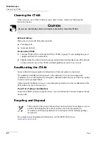
Page 85: ...uctuations Avoid unnecessary shocks and vibrations If any liquids are spilled on or into the unit turn off the power immediately disconnect from any external power source and let the unit dry complete...

Page 86: ...ug the power supply cord from the wall socket 2 Gently clean the connector end with the following instructions 2a Hold the can of compressed air upright and spray the can into the air to purge any pro...

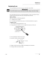
Page 87: ...d screwdriver 1 or 2 replacement fuses for fuse type see Technical Specifications on page 3 To replace a fuse 1 Turn off the unit and unplug the power cord 2 Using a flat head screwdriver as a lever p...

Page 88: ...ation validity period depends on the intensity of use and environmental conditions You can determine the adequate calibration interval for your CT440 according to your accuracy requirements Under norm...

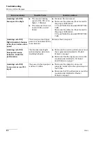
Page 89: ...ration Verify that optical connectors are clean Verify that optical connectors are properly connected to the CT440 PDL and tightly locked in position Use the 6 state PDL measurement method in the Scan...

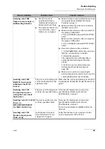
Page 90: ...and input power are not suited for the measurement Decrease the scan speed warning code 104 Unexpected source behavior check TLS performance The internal wavelength referencing has detected a troubli...

Page 91: ...ing on page 28 Make sure to perform a wavelength referencing operation in the laser see the corresponding laser user manual warning code 109 High TLS input power variations check TLS sources The power...

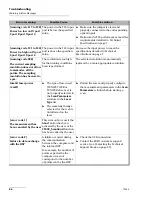
Page 92: ...on is automatically replaced by a more appropriate resolution Invalid laser power x mW The type of laser used TUNICS T100R or TUNICS Reference is not properly selected in the Scan Parameters window in...

Page 93: ...e port order error code 4 Switch failure Hardware failure on the optical switch Contact the EXFO customer support service see Contacting the Technical Support Group on page 89 error code 5 Failure in...

Page 94: ...t To activate the USB driver 1 Turn on the CT440 see Turning On Off the CT440 on page 21 2 Using the USB cable connect the USB A 2 0 port of your computer to the CT440 USB B connector located on the r...

Page 95: ...se have information such as the name and the serial number see the product identification label as well as a description of your problem close at hand Transportation Maintain a temperature range withi...

Page 96: ......

Page 97: ...he library located in two different folders one dedicated to 32 bit platforms and one dedicated to 64 bit platforms Each folder contains the following files CT440_lib dll is the main DLL CT440_lib h C...

Page 98: ...the same folder as your final executable DLL Updating the CT440 Library to the New Version v 1 1 x If you are using programs written with a previous library of the CT440 library you must make them com...

Page 99: ...D TO THE IMPLIED WARRANTIES OF MERCHANTABILITY AND FITNESS FOR A PARTICULAR PURPOSE IN NO EVENT SHALL EXFO BE LIABLE FOR SPECIAL INCIDENTAL OR CONSEQUENTIAL DAMAGES Liability EXFO shall not be liable...

Page 100: ...t covered by this warranty This warranty excludes failure resulting from improper use or installation normal wear and tear accident abuse neglect fire water lightning or other acts of nature causes ex...

Page 101: ...tions under which it was observed 5 Return the equipment prepaid to the address given to you by support personnel Be sure to write the RMA number on the shipping slip EXFO will refuse and return any p...

Page 102: ...ervices exfo service centers EXFO Headquarters Service Center 400 Godin Avenue Quebec Quebec G1M 2K2 CANADA 1 866 683 0155 USA and Canada Tel 1 418 683 5498 Fax 1 418 683 9224 support exfo com EXFO Eu...

Page 103: ...ICS T100S and T100S HP LS_TunicsT100r LS_JdsuSws LS_Agilent rLaserInput Laser input number on the CT440 front panel LI_1 LI_2 not applicable to models with only one input port LI_3 not applicable to m...

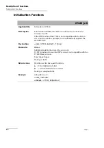
Page 104: ...p window prompts you to automatically upgrade the DSP firmware Declaration uint64_t CT440_Init int32_t iError Parameter iError Initialized variable that stores the error code 1001 produced in case the...

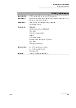
Page 105: ...ed 0 no CT440 is connected Data type int32 Example int32_t isCT440_connected isCT440_connected CT440_CheckConnected uiHandle CT440_Close Applicability All models of CT440 Description This function clo...

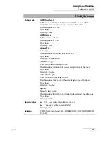
Page 106: ...eclaration int32_t CT440_SetLaser uint64_t uiHandle rLaserInput eLaser rEnable eEnable int32_t iGPIBInterfaceID int32_t iGPIBAdress rLaserSource eLaserType double dMinWavelength double dMaxWavelength...

Page 107: ...Data type rLaserSource dMinWavelength Laser minimum wavelength in nm Possible values minimum of the wavelength range of the laser Type Input Data type double dMaxWavelength Laser maximum wavelength i...

Page 108: ...nput Data type unsigned int64 eEnable Enables Disables the laser output Possible values see Data Types on page 97 Type Input Data type rEnable eEnable Enables Disables the laser output Possible values...

Page 109: ...of the laser connected to this port Declaration int32_t CT440_SwitchInput uint64_t uiHandle rLaserInput eLaser Parameters uiHandle Handle returned from CT440_Init Type Input Data type unsigned int64...

Page 110: ...ues depend on the laser s power specifications Type Input Data type double dMinWavelength Laser minimum wavelength in nm Possible values minimum of the wavelength range of the laser Type Input Data ty...

Page 111: ...be read from these ports Detector 1 is always enabled The number of enabled detectors impacts the number of points available for measurements see functions CT440_ScanGetWavelengthSyncArray on page 122...

Page 112: ...ues see Data Types on page 97 Type Input Data type rEnable eDect4 Enables Disables the detector 4 Possible values see Data Types on page 97 Type Input Data type rEnable eExt Enables Disables the Analo...

Page 113: ...PDL calculation Declaration int32_t CT440_Polstate uint64_t uiHandle int iState Parameters uiHandle Handle returned from CT440_Init Type Input Data type unsigned int64 eState State of polarization Pos...

Page 114: ...case the returned values represent the voltage at the port see functions CT440_ScanGetDetectorArray on page 130 and CT440_ScanGetDetectorResampledArray In the GUI this function corresponds to the Ana...

Page 115: ...V Possible values depend on the external power meter or detector used Type Input Data type double eUnit Units Possible values Possible values see Data Types on page 97 Type Input Data type rUnit Retu...

Page 116: ...T440 generates a pulse each time a measurement occurs For more details on this function see Synchronizing the CT440 with External Measurements on page 44 In the GUI this function is always enabled Dec...

Page 117: ...e Scan Parameters window On the T100S HP the BNC output must be activated as a trigger for more details see T100S HP User Manual Declaration int32_t CT440_SetExternalSynchronizationIN uint64_t uiHandl...

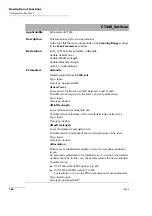
Page 118: ...w Declaration int32_t CT440_UpdateWavelengthReference uint64_t uiHandle double RefWavelength double MeasuredWavelength Parameters uiHandle Handle returned from CT440_Init Type Input Data type unsigned...

Page 119: ...ns in the Referencing window Declaration int32_t CT440_MeasureDark uint64_t uiHandle rDetector eDetector Parameters uiHandle Handle returned from CT440_Init Type Input Data type unsigned int64 eDetect...

Page 120: ...eclaration int32_t CT440_ResetDark uint64_t uiHandle rDetector eDetector Parameters uiHandle Handle returned from CT440_Init Type Input Data type unsigned int64 eDetector Front panel detector number P...

Page 121: ...ength referencing and on detector referencing In the GUI this function is identical to the Reset Calibration button in the Referencing window Declaration int32_t CT440_ResetCalibration uint64_t uiHand...

Page 122: ...r Before sending the command connect the CT440 output port directly to the selected detector with an SMF jumper Declaration int32_t CT440_UpdateCalibration uint64_t uiHandle rDetector eDetector Parame...

Page 123: ...or 6 states of polarization and be able to measure the PDL If the CT440_SetExternalSynchronizationIN function is used see page 111 the CT440 waits for a trigger signal from the laser on the Trigger In...

Page 124: ...a scan In the GUI this function corresponds to the Abort button when a start has been started Declaration int32_t CT440_ScanAbort uint64_t uiHandle Parameter uiHandle Handle returned from CT440_Init...

Page 125: ...int32_t CT440_ScanWaitEnd uint64_t uiHandle char tcError 1024 Parameters uiHandle Handle returned from CT440_Init Type Input Data type unsigned int64 tcError 1024 Initialized array that stores the de...

Page 126: ...ed variable to return the number of the laser currently scanning Type Input Output Data type rLaserInput allLasersProgress Pointer over an initialized variable to return the percentage of completion o...

Page 127: ...2 Example rLaserInput activeLaser rLaserInput calloc 1 sizeof rLaserInput int32_t allLasersProgress int32_t calloc 1 sizeof int32_t int32_t activeLaserProgress int32_t calloc 1 sizeof int32_t int32_t...

Page 128: ...the wavelengths for which a data point has been measured Declaration int32_t CT440_ScanGetWavelengthSyncArray uint64_t uiHandle double dArray int32_t iArraySize Parameters uiHandle Handle returned fro...

Page 129: ...ailed Data type int32 Example int32_t iArraySize CT440_GetNbDataPoints uiHandle double dWavelengthSync double calloc iArraySize sizeof double ScanGetWavelengthSyncArray uiHandle dWavelengthSync iArray...

Page 130: ...ach point Declaration int32_t CT440_ScanGetWavelengthResampledArray uint64_t uiHandle double dArray int32_t iArraySize Parameters uiHandle Handle returned from CT440_Init Type Input Data type unsigned...

Page 131: ...n failed Data type int32 Example int32_t iArraySize CT440_GetNbDataPointsResampled uiHandle double dWavelength double calloc iArraySize sizeof double ScanGetWavelengthResampledArray uiHandle dWaveleng...

Page 132: ...ion see Measurement Principle on page 3 Fills the input array with the measured values Declaration int32_t CT440_ScanGetPowerSyncArray uint64_t uiHandle double dArray int32_t iArraySize Parameters uiH...

Page 133: ...s 1 the operation failed Data type int32 Example int32_t iArraySize CT440_GetNbDataPoints uiHandle double dPowerSync double calloc iArraySize sizeof double ScanGetPowerSyncArray uiHandle dPowerSync iA...

Page 134: ...output power in each point Declaration int32_t CT440_ScanGetPowerResampledArray uint64_t uiHandle double dArray int32_t iArraySize Parameters uiHandle Handle returned from CT440_Init Type Input Data...

Page 135: ...ration failed Data type int32 Example int32_t iArraySize CT440_GetNbDataPointsResampled uiHandle double dPowerSync double calloc iArraySize sizeof double ScanGetPowerResampledArray uiHandle dPowerSync...

Page 136: ...rforms the following Gets the total number of measured transfer function points on a selected detector The step between points corresponds to the native resolution Fills the input array with the measu...

Page 137: ...he measured transfer function values Type Input Output Data type double iArraySize Size of the array The number of detectors used defined with CT440_SetDetectorArray on page 105 limits the available n...

Page 138: ...page 108 is set to DISABLE the value returned by the CT440_ScanGetDetectorArray function is the voltage measured at the Analog In BNC port Example int32_t iArraySize CT440_GetNbDataPoints uiHandle dou...

Page 139: ...a selected detector associated with the wavelength points produced by the CT440 The step between points corresponds to the resolution set in CT440_SetScan on page 104 For more details on re sampled da...

Page 140: ...led measured transfer function values Type Input Output Data type double iArraySize Size of the array The number of detectors used defined with CT440_SetDetectorArray on page 105 limits the available...

Page 141: ...DISABLE the value returned by the CT440_ScanGetDetectorResampledArray function is the voltage measured at the Analog In BNC port Example int32_t iArraySize CT440_GetNbDataPointsResampled uiHandle doub...

Page 142: ...y the CT440 in a text file The step between points corresponds to the native resolution Declaration int32_t CT440_ScanSaveWavelengthSyncFile uint64_t uiHandle char pcPath Parameters uiHandle Handle re...

Page 143: ...0_SetScan on page 104 For more details on re sampled data points see Measurement Principle on page 3 Declaration int32_t CT440_ScanSaveWavelengthResampledFile uint64_t uiHandle char pcPath Parameters...

Page 144: ...led detector s associated with the recorded pulse number Recorded values are those measured by the CT440 at the native sampling resolution Declaration int32_t CT440_ScanSavePowerSyncFile uint64_t uiHa...

Page 145: ...more details on re sampled data points see Measurement Principle on page 3 It also saves the re sampled transfer function measured on the enabled detectors Declaration int32_t CT440_ScanSavePowerSyncF...

Page 146: ...iated with the recorded pulse number Declaration int32_t CT440_ScanSaveDetectorFile uint64_t uiHandle rDetector eDetector char pcPath Parameters uiHandle Handle returned from CT440_Init Type Input Dat...

Page 147: ...r more details on re sampled data points see Measurement Principle on page 3 Declaration int32_t CT440_ScanSaveDetectorResampledFile uint64_t uiHandle rDetector eDetector char pcPath Parameters uiHand...

Page 148: ...g window Declaration int32_t CT440_ReadPowerDetectors uint64_t uiHandle double Pout double P1 double P2 double P3 double P4 double Vext Parameters uiHandle Handle returned from CT440_Init Type Input D...

Page 149: ...Input Output Data type double Vext Pointer over an initialized variable to store the voltage measured on the Analog In BNC port located on the rear panel Type Input Output Data type double Return valu...

Page 150: ...oints after a scan has been performed by the CT440 The index value of the trigger pulse associated with the first measured data point This index value corresponds to the total number of spurious pulse...

Page 151: ...r to a variable that stores the index of the trigger pulse associated with the first measured data point Type Input Output Data type unsigned int32 Return value 0 the operation succeeded 1 the operati...

Page 152: ...pled data points after a scan has been performed Declaration int32_t CT440_GetNbDataPointsResampled uint64_t uiHandle Parameter uiHandle Handle returned from CT440_Init Type Input Data type unsigned i...

Page 153: ...e dRefwithoutDUT double dDETwithoutDUT double dWLwithDUT double dRefwithDUT double dDETwithDUT double dWLadjusted double dIL double dPDL int32_t iTabsize Parameters uiHandle Handle returned from CT440...

Page 154: ...uble dWLwithDUT Pointer over an array containing the wavelength for each state during the measurement with DUT Type Input Data type double dRefwithDUT Pointer over an array containing the reference po...

Page 155: ...Output Data type double iTabsize Pointer over an initialized variable to store the size of dIL dPDL and dWLadjusted arrays Type Input Output Data type int32 Return value 0 the operation succeeded 1 th...

Page 156: ...number of spectral lines detected with heterodyne detection Declaration int32_t CT440_GetNbLinesDetected uint64_t uiHandle Parameter uiHandle Handle returned from CT440_Init Type Input Data type unsig...

Page 157: ...CT440_Init Type Input Data type unsigned int64 dArray Pointer over an initialized array Type Input Data type double iArraySize Size of the array Recommended value is the result of CT440_GetNbLinesDete...

Page 158: ...0 indicates the number of available inputs on the unit 1 the operation failed Example int32_t iNbofInputs CT440_GetNbInputs uiHandle CT440_GetNbDetectors Applicability All models of CT440 Description...

Page 159: ...n failed For more details on the operating wavelength range of each model type see Technical Specifications on page 7 Example int32_t CT440Type CT440_GetCT440Type uiHandle CT440_GetCT440Model Applicab...

Page 160: ...your computer Declaration int32_t CT440_GetCT440SN uint64_t uiHandle char SN 50 Parameters uiHandle Handle returned from CT440_Init Type Input Data type unsigned int64 SN 50 Allocated memory for stor...

Page 161: ...Handle int32_t iDSPversion Parameters uiHandle Handle returned from CT440_Init Type Input Data type unsigned int64 iDSPversion Pointer to a variable that stores the version of the DSP firmware Type In...

Page 162: ......
Page 163: ...computer and the CT440 has been established If the communication is established the configuration of the CT440 is carried out If the communication is not established the program ends by closing the c...

Page 164: ...pending on the language used LabVIEW results are displayed on graph and in a table C and Python results are saved in a xls file in the current folder 7 The communication between the CT440 and the comp...

Page 165: ...CT440_Reset Dark 114 CT440_ResetCalibration 115 CT440_ScanAbort 118 CT440_ScanGetDetectorArray 130 CT440_ScanGetDetectorResampledArray 133 CT440_ScanGetLineDetectionArray 151 CT440_ScanGetPowerResampl...

Page 166: ...able 15 plug 15 sources 16 power calibration 28 product identification label 89 specifications 7 pulses 45 R rear panel 10 referencing power 28 wavelength 30 regulatory information v repairing unit 15...

Page 167: ...quirements 79 89 trigger in 8 10 42 trigger out 8 10 44 triggered scan 42 troubleshooting 83 type of fuses 15 U unit 54 covers 15 disconnecting 15 installing 16 repairing 15 ventilation 16 unpack 17 U...

Page 168: ...ned in at least one of the homogeneous materials used for this part is above the limit requirement of GB T 26572 Due to the limitations in current technologies parts with the X mark cannot eliminate h...

Page 169: ...EXFO com info exfo com CORPORATE HEADQUARTERS 400 Godin Avenue Quebec Quebec G1M 2K2 CANADA Tel 1 418 683 0211 Fax 1 418 683 2170 TOLL FREE USA and Canada 1 800 663 3936 2019 EXFO Inc All rights rese...

Reviews: