background image

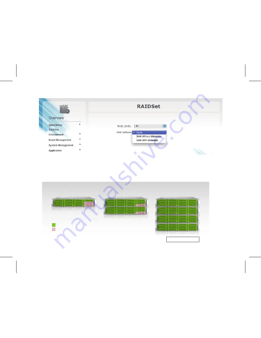
2. In the “RAID LEVEL” field, select “R5” from the drop-down list
3. In the “SAN Software” filed, select “SAN With MetaData” from the drop-down list

4. Click “Next”

*Quick Setup only supports one-to-four A12S-PS unit(s). If your RAID system requirement is anther form factor like 2U/3U/4U, you 

may have to reset the setting through RAID Guide X.  Please refer to the User Guide for RAID configuration information.

User Guide

P15

A12S2-PS X 1

A12S2-PS X 2

Disk1~10: R5 (Data)

R5 (Data)

Disk11~12: R1 (Metadata)

R1 (Metadata)

A12S2-PS X 4

with MDC codition

Summary of Contents for SW08-Q4

Page 1: ...et up SW08 Q4 PCIe Switch connection with A12S2 PS RAID system and clients using QFSP cables and HBAs Also includes software installation and setup information for ExaSAN SANit software 2012 V 1 0 June 2012 V 1 0 User Guide SW08 Q4 PCIe Switch ...

Page 2: ...Hardware 6 1 4 Connecting to a Power Source and Powering On 9 2 Software Installation and Configuration 11 2 1 ExaSAN Setup RAID GuardX RAID Configuration 12 2 2 Verify Accessible LUNs 17 3 SANit Setup 19 3 1 SAN Management software Installation 20 3 2 Connecting the Private LAN 20 3 3 SANit Configuration 21 4 Technical Support 39 4 1 The System Log 40 4 2 Contact Us 40 4 3 Our Website 40 ...

Page 3: ...User Guide Hardware Installation 1P1 ...

Page 4: ...ExaSAN Solution setup FIGURE 1 Sample ExaSAN Solution Architecture Although it is not practical to cover all possible scenarios in this guide most variations of the system configuration can be derived from this sample If your particular installation encounters a problem that is beyond the scope of this guide please contact our technical support staff for assistance User requires a system with DDR2...

Page 5: ...S RAID disk system one unit purchased separately 2 ExaSAN PCIe Switch SW08 Q4 one unit 3 ExaSAN PCIe Switch Host Bus Adapters one for each supported workgroup client system purchased separately 4 QSFP PCIe copper or optical cables for connecting the switch to the workgroup client systems one for each client system 5 Power cords one for the RAID system and another for the switch 6 CAT 5 cable for t...

Page 6: ...8 host systems and PCIe 2 0 RAID systems Power cord for the SW08 Q4 switch CAT 5 cable for the LAN port of SW08 Q4 switch RAID Guard X configration 2 QSFP copper or optical cable Option 20Gb QSFP copper 2M 5M or optical cable 10M 30M 50M 100M connects SW08 Q4 switch to QSFP HBA on host P4 ...

Page 7: ...kage A12S2 PS 20Gb PCIe 2 0 12 bay RAID system supports SATA and SAS drives Power cord for A12S2 PS RAID system 2M 20Gb QSFP cable connect A12S2 PS RAID system to the SW08 Q4 Switch P5 Note User Guide and CD containing the A12S2 PS User Manual are also included in the SW08 Q4 package ...

Page 8: ... the A12S2 PS User Manual for instructions Step 3 Installing HBA Step 4 Connecting Switch to the RAID Disk System Step 5 Connecting Switch to the Host Systems Step 6 Connecting the Switch LAN Step 7 Power on sequence Step 8 Create Array for SAN Configuration Step 9 SAN Software Installation Step 10 SAN Configuration 1 3 Setting up the Hardware 1 3 1 Installing the HBA Before the ExaSAN Compact Sol...

Page 9: ...er or not the HBA card was just purchased or originally used in storage In this case the HBA card is used for connecting the Compact Switch Please make sure the switch button is toward the 1 position as shown below 3 Position the connector of the card over the slot insert the connector into the slot press gently but firmly until it is securely seated 4 Secure the metal bracket of the card to the s...

Page 10: ...ctivity of up to four A12S2 PS RAID units 1 Connect your RAID storage unit to the ExaSAN SW08 Q4 Switch with an QSFP cable Insert one end of the PCIe cable into the PCIe port on the back of the RAID system Your cable connector is securely plugged when you hear a click If you need to unplug the cable pull the ring on the connector firmly until it is detached from the port 2 Insert the other end of ...

Page 11: ...A which you installed on the client system earlier in Section 1 3 1 3 Repeat steps 1 and 2 for client systems 2 4 Plug a power cord into the AC power in port on the rear panel of the switch Do not turn power on yet 1 4 Connecting to a Power Source and Powering On Before powering on make sure that all cables and cords are properly installed and connected 1 If not yet plugged into the wall electrica...

Page 12: ...for the Heartbeat LED to turn into a steady flashing blue light Note that you might hear a few short beeps generated from the switch during this process You may ignore them as they are designed for Accusys internal diagnostic purposes only 4 Finally power on the client workstation computer system User Guide P10 No Name 1 Cooling Vents 2 Power LED Indicator 3 Access LED Indicator 4 Fan LED Indicato...

Page 13: ...Software Installation and Configuration 2 User Guide P11 ...

Page 14: ... Setup The ExaSAN switch has a browser based built in GUI Graphical User Interface for administration and configuration tasks 2 1 2 Launch the Switch GUI You may use either the FireFox or Safari browser to access the switch GUI We recommend that you use FireFox 1 Launch the browser of your choice 2 Make sure that our private Ethernet network is connected 3 Go to IP address 192 168 0 1 4 The GUI s ...

Page 15: ...h GUI main menu page You may toggle between Config Mode and Monitor Mode by clicking the Switch Mode icon at the top You may also go into System Management to change the switch IP and password or to set system date and time User Guide P13 Switch Mode ...

Page 16: ...u should set your system date and time first 2 1 4 Quick Setup We will create two LUNs in the RAID disk system One is for the Xsan metadata and the other for the user data 1 Select Quick Setup from the menu options on the left pane to start the process User Guide P14 ...

Page 17: ...p only supports one to four A12S PS unit s If your RAID system requirement is anther form factor like 2U 3U 4U you may have to reset the setting through RAID Guide X Please refer to the User Guide for RAID configuration information User Guide P15 A12S2 PS X 1 A12S2 PS X 2 Disk1 10 R5 Data R5 Data Disk11 12 R1 Metadata R1 Metadata A12S2 PS X 4 with MDC codition ...

Page 18: ...s in your RAID storage system During this process you may experience deterioration in overall system performance this is normal Please allow sufficient time and patience for this process Upon completion the LED indicators on the front panel of your RAID system will reflect that status Refer to the appropriate documentation of your RAID system for additional information User Guide P16 ...

Page 19: ...isible as described below Find one LUN in SCSI target Device 0 another LUN in SCSI Target Device 1 Both are identified with Manufacturer ACCUSYS and Model A12S2 PS Note that you will need to perform this check on all computers in the SAN If you do not see any LUN here you d have to troubleshoot the connection between the ExaSAN R AID system and the SW08 Q4 switch User Guide P17 ...

Page 20: ...User Guide P18 ...

Page 21: ...SANit Setup 3 User Guide P19 ...

Page 22: ...r the SAN must be connected to a private Ethernet network the Private LAN SANit MDC servers and clients use this network to exchange file system metadata Connect each SAN client and MDC server to two Ethernet networks one private subnet for the SAN metadata and a separate connection for directory service intranet and Internet traffic the Public LAN The steps below apply to the Private LAN only We ...

Page 23: ...Nit Configuration 1 Enter your MDC IP address in the URL of your computer and then enter port number 85 See below http MDC IP address 85 for example http 10 10 88 10 85 2 Select Language enter User Name and Password Default password is 0000000 and then click Log In Software Installation file on MDC The following is installation command 1 The file name is SANIT 5 3 3 450 x86_64 rpm Example version ...

Page 24: ...Active SANit 1 License import 2 SAN Volune 3 SAN client 4 SANit client install set up 3 3 1 Import License 1 Click License and then Import User Guide P22 ...

Page 25: ...2 Enter import file name and then click Evaluate 3 Click Import User Guide P23 ...

Page 26: ...4 See the information shown below User Guide P24 ...

Page 27: ...u Select Metadata and Data volume devices using the boxes as shown below Enter Yes in the configure box below and click Continue User can re name the SAN volume If you can t see the same amount of your volume on the screen then do Rescan button User Guide P25 ...

Page 28: ...8 After configuration is 100 completed see the information below User Guide P26 ...

Page 29: ...3 3 3 Add SAN Client 1 Click Client Management and click Add 2 Enter your computer s IP address in Client IP box User Guide P27 ...

Page 30: ...states of the added clients 3 3 4 Client Install Set up 1 Click Client Software and Document Downloadation Chose what client software that you need then install it Make sure that you have seen the RAID Volume then you can do the installation User Guide P28 ...

Page 31: ...in your computer Select Device Management and then select Disk drives Confirm that the device with installed driver appears in Disk drive as shown below If you can t see the client you created then you can t mount SAN volume User Guide P29 ...

Page 32: ...3 Continue installation using the FS Client 5 3 3 Setup Wizard by clicking Next User Guide P30 ...

Page 33: ...4 Enter the Destination Folder and click Next User Guide P31 ...

Page 34: ...5 Enter the folder name FS Client is the default name or you may choose and then click Install User Guide P32 ...

Page 35: ...6 Select Reboot now and click Finish Computer system will then reboot User Guide P33 ...

Page 36: ...he Start menu in the lower left side of your computer screen and select All Programs Select the FS Client Or other folder name see Enter the folder name and click Install and then select FS Client User Guide P34 ...

Page 37: ... See the screen below Click Server and then right click Add Server 9 Enter your computer s server IP Address Use the same IP address of your computer MDC Metadata Controller Then click OK User Guide P35 ...

Page 38: ...10 Select the server IP Address and then right click Connect Server User Guide P36 ...

Page 39: ...the SAN volume path and then right click Mount 12 Finally click the Computer icon on your desk top See client local hard disks and SAN hard disk storage location and capacity status as shown below User Guide P37 ...

Page 40: ...P38 User Guide ...

Page 41: ...User Guide Technical Support 4P39 ...

Page 42: ...nt icon Follow instructions there to download the log file 4 2 Contact Us For customer services and technical support locate an Accusys office near you from the link below http www accusys com tw about contact htm or you may e mail us at support accusys com tw 4 3 Our Website Please visit our websites frequently for the most up to date product and support information All countries www accusys com ...

Page 43: ......

Page 44: ...Quick Start Guide 42 33000 5041 ...

Reviews: