background image

XRD9829REF

4

Rev. 1.00

OPERATIONAL PROCEDURE

The routine listed below will first calibrate the photo response of the CIS using the XRD9829.
After calibration, the XRD9829REF can be used to scan any color target to show CIS non-color
corrected response.  (Color correction is typically done in the digital asic.)

How to Run the XRD9829REF Demonstration:

1. Make sure the computer is powered off and the AC power adapter is disconnected from a

wall outlet

2. Connect the parallel port cable to the printer port of the computer
3. Connect the AC power adapter into a wall outlet
4. Turn on the computer and activate Windows 95

Loading EXAR Software

5. Load the diskette labeled ScanIt 1.0 Disk # 1 into the floppy drive
6. Select the Start menu in the program manager and choose RUN
7. Inside the small pop-up window, type:  A:\setup
8. Follow the instructions to finish software installation

CLP

VIN0
VIN1
VIN2
VIN3

VREF+

DB4:0 / DB9:5

DVDD

PDB

LD

DGND

AVDD

AGND

ADCCLK

PGA

CONTROL LOGIC

AVDD

6-BIT GAIN

REGISTER

10-BIT

ADC

RL

AGND

DATA

OUT

PORT

BUFFER

VRT

VRB

4-1

MUX

8-BIT DAC

10

5

8-BIT OFFSET

REGISTER

6

8

+

_

AGND

V

DCEXT

SCLK
SDATA

V

DCREF

DC/AC

MUX SEL

INT/EXT_V

DCREF

CIS/CCD

G<5:0>

O<7:0>

VRT

CCD

CIS

Power

Down

Power

Down

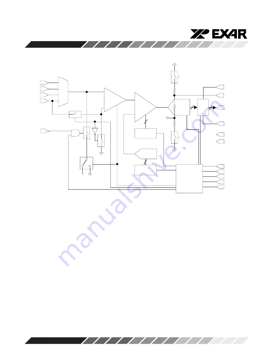
Figure 2.  Functional Block Diagram of XRD9829

Summary of Contents for XRD9829REF

Page 1: ...EXAR Corporation 48720 Kato Road Fremont CA 94538 510 668 7000 FAX 510 668 7017 July 1998 2 XRD9829REF USER MANUAL CIS 30 BIT COLOR SINGLE LINE SCANNER...

Page 2: ...10 bit Linear CIS CCD Sensor Signal Processor to get a single line scan The XRD9829REF is designed to provide a signal path for the CIS output signals to be processed digitized by the XRD9829 and tra...

Page 3: ...ORT CONTROL DC 1 25V MACH435 CPLD CIS OUTPUT Figure 1 Block Diagram of XRD9829REF The XRD9829 is a complete linear CIS or CCD sensor signal processor on a single monolithic chip The XRD9829 includes a...

Page 4: ...power adapter into a wall outlet 4 Turn on the computer and activate Windows 95 LoadingEXARSoftware 5 Load the diskette labeled ScanIt 1 0 Disk 1 into the floppy drive 6 Select the Start menu in the p...

Page 5: ...uter as advised 10 If you do not have a Printer Port configured on your computer please follow the steps listed below a From the Control Panel window which pops up double click on Add New Hardware b F...

Page 6: ...XRD9829REF 6 Rev 1 00 S 1 S 0 D 5 D 4 D 7 D 6 D 1 D 0 D 3 D 2 1 0 Figure 3 Dip Switches Set to Value 1100010000 to Reset the XRD9829...

Page 7: ...ERNAL 1 1 VIN3 1 1 VIN3 VDCREF VDCEXT Mode Test 11 X X X DIGITALRESET TEST3 TEST2 TEST1 X XXX0000X 0 NO RESET 0 TEST3 0 TEST2 0 TEST1 1 RESET DISABLED DISABLED DISABLED REGISTERSARE 1 OUTPUT 1 OUTPUT...

Page 8: ...of Captured Data and the lower window shows the Histogram of data Figure 3 shows the pop up window when ScanIt is first s t a r t e d Figure 4 ScanIt Software Window Before Scanning 14 Select SETUP fr...

Page 9: ...A typical result of a black target scan is shown below Figure 5 Non calibrated Black Target Scan 16 Set the dip switches to 1000010000 to select the external DC reference for the 1 25V global offset a...

Page 10: ...XRD9829REF 10 Rev 1 00 Figure 6 Black Target Scan After Global Offset Adjust...

Page 11: ...xternalResistorLadder 17 Set the dip switches to 0111000000 to select the internal offset DAC for fine offset adjustment Push the Serial Port button From the CAPTURE menu select SNAP SHOT The offset s...

Page 12: ...XRD9829REF 12 Rev 1 00 Figure 8 Black Target Scan After Global and Fine Adjust...

Page 13: ...DAC Figure 9 Simplified Block Diagram Showing Fine Offset Adjustment by XRD9829 18 Switch the black target to the enclosed white target From the CAPTURE menu select SNAP SHOT for a single line scan o...

Page 14: ...e desired gain Push the Serial Port button From the CAPTURE menu select SNAP SHOT The gain should move the output of the CIS to almost full scale Please refer to data sheet for further gain adjustment...

Page 15: ...XRD9829REF 15 Rev 1 00 Figure 11 White Target Scan After Gain Adjustment...

Page 16: ...Gain Register Figure 12 Simplied Block Diagram Showing Gain Adjustment by XRD9829 20 Once the XRD9829 has been fully calibrated any target can be scanned For example Scan a gray scale to demonstrate...

Page 17: ...is shown or the demo system seems to not working please pull the AC adapter out from the wall outlet to cycle power Start the procedures again from Step 11 2 Keep the scanner away from other electric...

Page 18: ...XRD9829REF 18 Rev 1 00 SchematicsforXRD9829REF Page 1 of 3...

Page 19: ...XRD9829REF 19 Rev 1 00 SchematicsforXRD9829REF Page 2 of 3...

Page 20: ...XRD9829REF 20 Rev 1 00 SchematicsforXRD9829REF Page 3 of 3...

Page 21: ...XRD9829REF 21 Rev 1 00 Notes...

Page 22: ...XRD9829REF 22 Rev 1 00 Notes...

Page 23: ...XRD9829REF 23 Rev 1 00 Notes...

Page 24: ...checked no responsibility however is assumed for in accuracies EXAR Corporation does not recommend the use of any of its products in life support applications where the failure or malfunction of the...

Reviews: