background image


EX-TECH-SIG-SAS-12-SD125-150-TM-EN-REV04 

Pressing


Times


Default Setting


Option


1


1 minute 

10 minute 

2


5 minute 

30 minute 

3


10 minute 

60 minute 


4


Restore to the 

sound 

Restore to the 

sound 


7.0  TONE SELECTION


The  sounder  provides  63  tones  to  be  selected  for    the 

alarm  stage  2  to  4.  Three  stages  of  alarm  tones  can  be 

preset via switch on the Sounder PCB. 


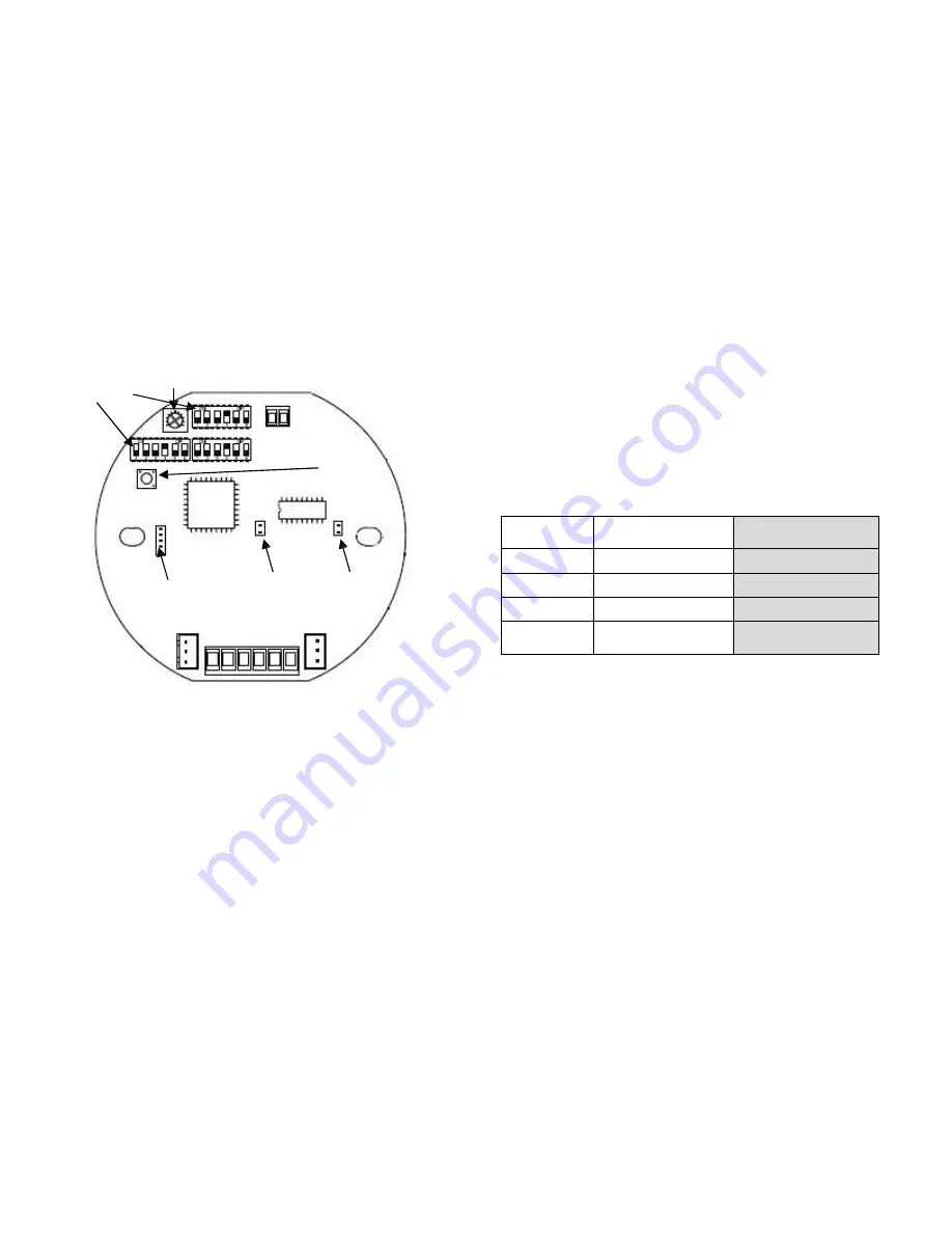
Tone Selection Switch


Use the three (3) DIP switches with 6 binary codes on the 


Sounder PCB 

to select tones (See Fig 3). 


Tone Selection Table (see attached table 1)


DIP Switch 

Potentiometer


Recording Procedure 


1.  Turn off S1 and S2; 


2.  Set up any DIP Switches as Tone 60-63 (refer to 

Attached Table 1- Tone Selection Table); 

3.  Insert the Audio IN plug; 


4.  Press  the  Recording  Button  and  hold  the  button 

until the recording is finished. 


CAUTION: 

The  sounder  will  begin  to  record  after  3 

seconds from pressing the button. Don’t release the button 

when  the  recording  is  in  process.  The  maximum  of 

recording time is 20 seconds. 


10.0 SOUND PAUSE


The  sound  can  pause  by  pressing  the  Recording  Button. 

(See Fig 3) 


As the pausing period, please refer to the below table: 


In order to have the option function, please inform EX-

TECH SIGNALLING SAS in advance before EX-TECH 

SIGNALLING SAS begin the production of the sounder. 


11.0 CABLE GLAND


8.0  VOLUME CONTROL


The  sounder  has  a  volume  control  to  adjust  the  output 

volume  of  the  sounder  component.  To  set  the  required 

output  volume,  adjust  the  potentiometer-VR1  on  the  PCB 

(See  Fig  3).  The  potentiometer  should  be  set  to  fully 

clockwise position if maximum output volume is needed. 


9.0 SOUNDER RECORDING


The  sounder  can  provide  4  tones  can  be  recorded  by  the 

user.  Use  the  Audio  In  and  Recording  Button  (See  Fig  3) 

to record. 

The  SD150  series  product  has  cable  gland  entries. 

Only cable glands approved for  Ex  ‘d’  applications  can 

be used, which  must  be  suitable  for  the  type  of  cable 

being  used and  also  meet  the  requirements  of  the  Ex 

‘d’  flameproof installation standard EN/ IEC 60079-14. 


SAFETY WARNING: 

If the SD150 is used at high ambient 

temperatures,  i.e.  over  +40ºC,  then  the  cable  entry 

temperature  may  exceed  +70ºC  and  therefore  suitable 

heat  resisting  cable  glands  must  be  used,  with  a  rated 

service temperature of at least 95ºC. 


If  a  high  IP  (Ingress  Protection)  rating  is  required,  a 

suitable  sealing washer  must  be  fitted  under  the  cable 

gland. 


When only one cable entry is used, the other one must be 

closed with an Ex ‘d’ flameproof blanking plug, which must

Recording Button


Reset


Pause Button


Audio In


 L  N  S0 S1 S2 DIY 

Fig 3 

Summary of Contents for SD125

Page 1: ...P66 Ex tb IIIC Txxx EX TECH SIGNALLING SAS SD125 150 EXPLOSION PROOF SOUNDER HORN TECHNICAL MANUAL Marking details Please note that every care has been taken to ensure the accuracy of our technical ma...

Page 2: ...Warning DO NOT OPEN WHEN AN EXPLOSIVE GAS ATMOSPHERE IS PRESENT Finish product serial no Include date of construction Note exact information is given on the actual label ref also example on page 1 3...

Page 3: ...ioned such that dust debris or water cannot enter into the horn opening but operate in reverse manner as above 6 0 WIRING General Requirement EX TECH SIGNALLING SAS recommends that all cables and core...

Page 4: ...m EX TECH SIGNALLING SAS in advance before EX TECH SIGNALLING SAS begin the production of the sounder 11 0 CABLE GLAND 8 0 VOLUME CONTROL The sounder has a volume control to adjust the output volume o...

Page 5: ...exterior of the product can be cleaned with a damp cloth If spare parts are required these can be supplied by EX TECH SIGNALLING SAS Company SAFETY WARNING In the case of Anti Static and UV Resistant...

Page 6: ...EX TECH SIG SAS 12 SD125 150 TM EN REV04 Attached Table 2 Tone Selection Table 6...

Page 7: ...S 12 SD125 150 TM EN REV04 EX TECH SIGNALLING SAS ZA Les Montagnes 355 rue de la G noise 16430 CHAMPNIERS France Tel 33 5 45 61 81 68 Fax 33 5 45 23 29 46 Website www ex tech no E mail sales signallin...

Page 8: ...Hz 2s on 2s off Intermittent Air raid Sweden 105 101110 890 86 30 700Hz 125ms on 125ms off Intermittent Local Warning Sweden 105 011110 875 87 31 720Hz 0 7s on 0 3s off Intermittent Industrial alarm G...

Page 9: ...is on 4 The unit will alarm as stage 1 when switch 1 is on The unit will alarm as stage 2 when switch 2 is on The unit will alarm as stage 3 when switches 1 2 are on Telephone Initiated PCB Function...

Page 10: ...The unit will alarm as stage 2 when switch 2 is on The unit will alarm as stage 3 when switches 1 2 are on Telephone Initiated PCB Function 1 Connect the telephone line to the Tel terminals 2 The unit...

Reviews: