support.ewon.biz
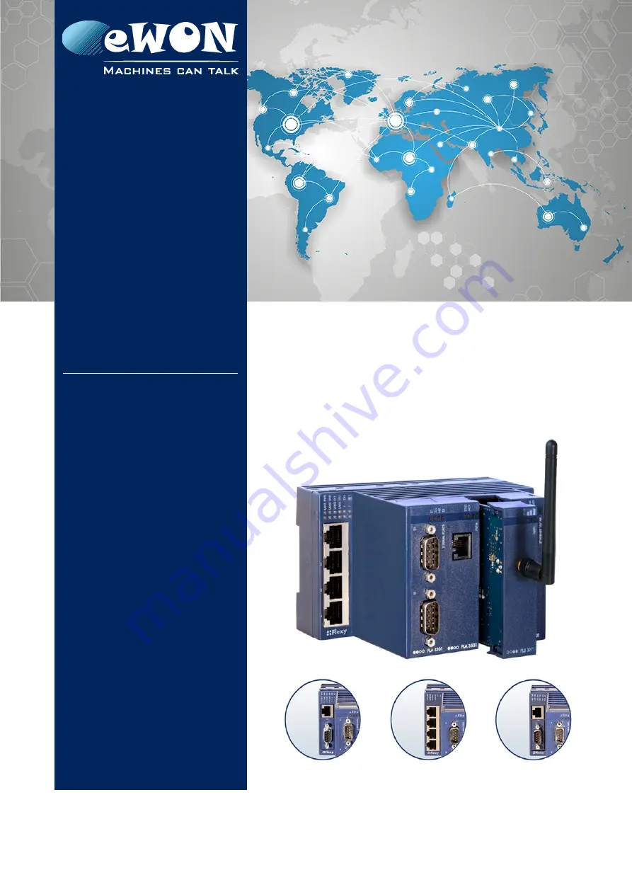
eWON Flexy - Base Units
This installation guide describes the hardware of the eWON Flexy - Base Unit and explains how to get started with the embedded web site.
Installation Guide
IG 014 / Rev. 1.5
Page 1: ...port ewon biz eWON Flexy Base Units This installation guide describes the hardware of the eWON Flexy Base Unit and explains how to get started with the embedded web site Installation Guide IG 014 Rev...
Page 2: ...5 1 Purpose and Reference 10 2 5 2 Battery Replacement Procedure 11 2 6 Field Implementation Environmental Conditions 12 2 6 1 Ingress Protection 12 2 6 2 Mounting Recommendations 12 2 6 3 Earthing 1...
Page 3: ...Factory Default IP settings 28 5 2 Powering ON 28 5 3 Setting the eWON Flexy LAN IP Address 28 5 4 eWON Flexy s Web Interface 30 5 5 Detected Cards Displayed in the System Page 30 6 Resetting the eWO...
Page 4: ...Ethernet Wifi 3G and securing the investment in case of technology upgrade eg 2G 3G Flexible Field providing easy connection to a wide range of external devices including various field protocols Flex...
Page 5: ...ication interface 2 Ethernet Switch Flexy 101 201 Serial Ethernet Flexy 102 202 MPI Ethernet Flexy 103 203 Each Base Unit features two DI and one DO 3 four free slots allowing to add Extension Cards 4...
Page 6: ...HTTP client HTML Get Put requests Ethernet to Serial gateway Routing between Ethernet interfaces WAN to LAN Routing features IP forwarding NAT Port forwarding 1 4 General specification of the hardwar...
Page 7: ...e part numbers are Part Number Type Description FLEXY10100_00MA Flexy 101 M2M Data Gateway Ethernet Only Switch 4 Ports FLEXY10200_00MA Flexy 102 M2M Data Gateway Ethernet Serial FLEXY10300_00MA Flexy...
Page 8: ...llation Guide are partially exposed when slot fillers are removed to place Extension Cards In order to avoid ESD damage the product when it is opened must be handled with the necessary precaution incl...
Page 9: ...ds IEC EN 60950 1 UL 60950 1 CSA C22 2 No 60950 1 07 2 3 3 FCC Compliance The Base Units and these Extension Cards comply with Part 15 of the FCC Rules Operating is subject to the following two condit...
Page 10: ...ence Standard Programmable controllers test IEC 61131 2 Vibration test sinusoidal IEC 60068 2 6 Vibration test broad band random IEC 60068 2 64 Shock test IEC60068 2 27 2 5 Internal Battery 2 5 1 Purp...
Page 11: ...To have a practical access it is recommended to remove all slot fillers and or Extension Cards It is feasible but less comfortable to remove only the slot filler or Extension Card of slot 3 Carefully...
Page 12: ...Present the unit in front of the DIN rail and tilt it upwards in order to hang it on the upper edge of the DIN rail by the hooks at the rear Gently tilt the unit downwards until the slide lock snaps T...
Page 13: ...4 Environmental Limits The equipment will operate properly within following environmental limits provided it is mounted according to the above mentioned recommendations Characteristic Value Operating...
Page 14: ...housing The different parts of the label are described below PN Part Number see syntax in table below SN Serial Number YYWW SSSS PP YY 2 last digits of production year WW production week number SSSS S...
Page 15: ...Define primary software option 00 No primary software option 44 2 numeric signs Define secondary software option 00 No secondary software option AA 2 alphabetic signs CAPS Define the firmware languag...
Page 16: ...ed areas show provisions of empty space that should be considered in the implementation arrangement The provision of empty space in front of the slot fillers is for the connectors of Extension Cards E...
Page 17: ...explained subsequently in separate paragraphs LED panel RESET button BI1 SD card slot Main connector used to connect the power supply and the digital inputs outputs 4 slots fillers that can be remove...
Page 18: ...faces of each model 3 3 2 Reset Button The reset button allows to reset the Base Unit partially or completely For the reset procedures check 6 Resetting the eWON Flexy 3 3 3 SD Card Currently not supp...
Page 19: ...TP Class 5 direct and crossed cables with RJ45 terminations at both ends Default parameters see 5 1 Factory Default IP settings The minimum required Ethernet cable type is Cat 5 with RJ45 connectors L...
Page 20: ...h ends Default parameters see 5 1 Factory Default IP settings 3 3 7 2 Serial Port The configuration of the physical serial mode is done via the eWON software configuration Possible configurations are...
Page 21: ...u can use both UTP Class 5 direct and crossed cables with RJ45 terminations at both ends Default parameters see 5 1 Factory Default IP settings 3 3 8 2 MPI Port The MPI Profibus port allows to connect...
Page 22: ...oth type A and type B slots Others don t Cards that fit in only one type of slot have a mechanical Poka Yoke security The reference code of the Extension Cards includes a letter that defines their com...
Page 23: ...mbol on its front panel The visual symbols are shown in the table below 2 first slots only A In any slot X 2 last slots only B An example of hardware configuration is shown in the picture below Base U...
Page 24: ...ered like shown on the pictures Hooks to be pressed are off centered press while pulling upwards This metal tag soldered on the PCB acts as mistake proof security mating stop in housing Insert the Ext...
Page 25: ...and OFF The Extension Card types are detected slot per slot during the boot sequence and are automatically installed from a system standpoint If an Extension Card was inserted in a wrong slot the boo...
Page 26: ...ons of Extension Cards Users should make sure the total power demand of the Extension Cards does not exceed the capabilities of the Base Unit That is why the notion of Energy Points has been introduce...
Page 27: ...101 3G GSM FLB 3202 Energy Demand Points 1 1 10 Table of the Energy Demand Points for 3 types of Extension Cards 4 5 3 Power Balance Check Example Considering the configuration shown in the second pic...
Page 28: ...cted on the LAN Network USR LED falshing pattern is RED 1x short 1x long For the other LED patterns in case of error please refer to the General Reference Guide RG 001 5 3 Setting the eWON Flexy LAN I...
Page 29: ...IP Address Fill out the Serial Number of your Flexy or click on Browse and select it The Serial Number of the Flexy is on its label see 3 1 Base Unit Label Click Next Enter new LAN IP address and Sub...
Page 30: ...is opening Warning For security reasons changing the default password adm is an absolute necessity To change the adm password from the menu bar click on Configuration Users Setup and double click on t...
Page 31: ...part of the non volatile memory This type of reset does not modify the communication parameters of the eWON Flexy How do I generate a first level reset Power the unit OFF and ON again Immediately pre...
Page 32: ...s NOT restart in normal mode by itself and remains running in this diagnose mode You have to power the eWON Flexy OFF and ON again to reboot the unit in normal mode As described before the eWON return...
Page 33: ...way config Talk2M config key eWON Identification Proxy configuration User Web site Memory configuration User Scripts Impact Reset Level 2 factory reset LAN IP address mask Nothing Internet access Lang...
Page 34: ...plementation Environmental Conditions Power in GND 0V Power in VDD between 12 et 24 VDC Related specification see below Digital Inputs i2 Input signal 2 Related specification see below i1 Input signal...
Page 35: ...ivalents are available on the market Characteristic Value Power supply voltage external 12 24 VDC 20 Max input power 30W max Internal voltage protection max 30V Input protection protected against pola...
Page 36: ...al wiring needed for correct operation of the digital output A relay has been chosen for this sample application but any load within the specifications can be used instead Note This is a sink only out...
Page 37: ...eristic Value Physical mode MPI 1500V galvanic isolation through the power supply isolation from ground Baud rates From 9 6 kBauds to 12 0 MBauds Polarization 100 k Termination None SUBD9 female conne...
Page 38: ...ts 2 Refere nce Available Energy Points 2 M2M Router Flexy 201 20 Flexy 202 21 Flexy 203 22 M2M Data Gateway Flexy 101 20 Flexy 102 21 Flexy 103 22 B 2 Extension Cards Picture Reference Name Slot comp...
Page 39: ...ed in 4 4 2 Software Compatibility of Multiple Card Combinations the number of cards of the same type that are supported by the firmware is limited to the number stated in this column 2 As explained i...
Page 40: ...es No liability or warranty explicit or implicit is made concerning the quality the accuracy and the correctness of the information contained in this document In no case the manufacturer s responsibil...